Table of Contents
The SS-PWM peripheral provides a specialized Pulse Width Modulation scheme (PWM) for multilevel converters, which directly integrates means for balancing series-connected submodules. Such an approach has received quick and widespread adoption, notably for Modular Multilevel Converters, Cascaded H-Bridges, and similar converter topologies.
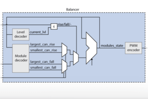
The SS-PWM block generates gate driving signals, which are dynamically assigned to suitable submodules following a “Sort and select” algorithm. The corresponding operating principle is relatively simple:
- At first, submodules are sorted according to their capacitor voltage.
- Then, the submodules selected to contribute to the arm voltage are those with the highest charge level when the power is flowing out of the arm, respectively with the least charge level when the power is flowing into the arm. This way, some balancing is achieved over time so that all submodules converge toward the same charge level.
Multilevel PWM operation
The FPGA-based implementation of the SS-PWM is detailed in TN160. It is inspired by the original patent by R. Marquardt. The implemented multilevel modulator features the following key characteristics:
- All submodules are continuously sorted. In other words, all ranks are identified, as opposed to techniques that only identify the most and least charged submodules.
- By design, it is guaranteed that only one commutation can occur at once. This ensures that no ineffective modulation actions are made and that switching losses are minimized.
- Both half-bridge and full-bridge submodules are supported.
- Up to N=23 submodules per arm are supported.
- Both PWM and staircase modulation approaches are supported.
Similarly to other PWM modules, the following parameters of the multilevel PWM module can be configured:
- The sampling frequency is freely configurable (identical to the control interrupt frequency).
- The switching frequency is freely configurable.
- PWM update is possible once or twice per period (when the carrier reaches its minimum and/or maximum).
- Complementary High and Low signals offer a configurable dead-time generation.
- Multilevel PWM outputs can be activated or deactivated during the operation.
Simulink SS-PWM block
Signal specification
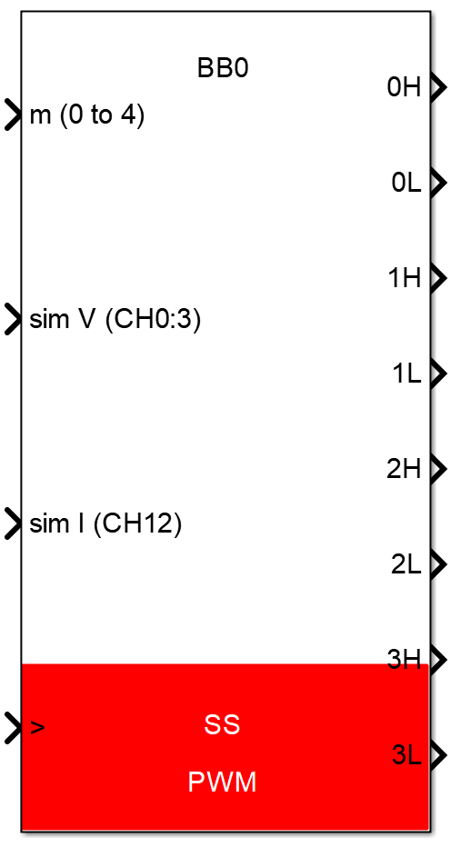
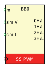
- The input
mis the modulation signal. Its range is [0; N] inhalf-bridgemode and [-N; N] infull-bridgemode. N is the number of submodules per arm. - The input signal
sim Vis a vector containing the submodules voltages. This input is only effective during simulation. Measurements are directly taken from the corresponding analog input channels during real-time operation. - The input signal
sim Icorresponds to the arm current and is only used for simulation. - The input signal
>is the clock input and must be connected to the CONFIG block or to an independent CLK block. When connected to a variable-frequency clock, the switching frequency can be tuned during runtime (see PN121). - The outputs are the generated PWM signals, according to the block configuration. The outputs are only used for simulation.
Parameters
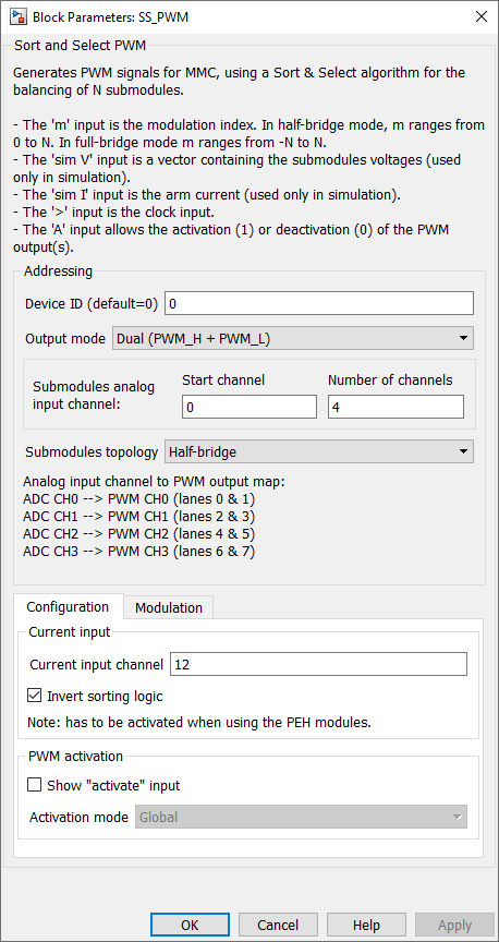
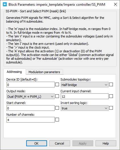
Device IDselects which B-Box/B-Board to address when used in a multi-device configuration.Output modeselects between complementary signals with a deadtime, a single PWM with a global active signal or a single PWM.Start channelandNumber of channelsdefines the number of submodules per modulator, with a maximum of 23 modules, by specifying the analog input channels. Each analog input channel correspond to one submodule. The PWM outputs are automatically assigned to each analog input.
B-Box 3: The maximum number of submodules and the corresponding input channels are limited to 8.Submodules topologydefines if the modules are half-bridge or full-bridge modules.Current input channelselects the analog input channel of the arm current measurement.
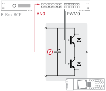
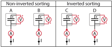
B-Box 3: The current input channel must be between 8 and 15.Invert sorting logicinverts the sorting logic of the SS-PWM sorting algorithm. As described by the schematic below, if a positive/negative measured current results in an increase/decrease of measured voltage, respectively, then the logic is non-inverted. On the other hand, the sorting logic must be inverted if a positive/negative measured current results in a decrease/increase in measured voltage, respectively. Also, this parameter being purely defined by the hardware, it is only used for code generation and has no effect in simulation mode.Show "activate" inputmakes theA(active) signal input visible. If not checked, the SS-PWM block is always active by default (once the controller outputs are enabled).Activation modespecifies if the activate input is global or per submodule. In the global mode, the activate signal is one-dimensional and applied to all submodules. In the per submodule mode, the activate signal is an array with one signal per submodule.
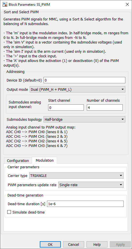
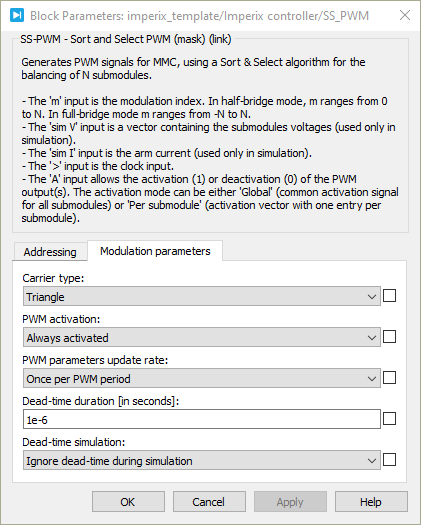
B-Box 3: Only the global mode is supported and the option is therefore not shown.- Carrier type sets the carrier to TRIANGLE, INVTRIANGLE, or No Carrier (Staircase modulation). This option can be used to either generate N+1 or 2N+1 level output waveforms.
PWM parameters update rate- Single-rate: they are applied at the end of the carrier period.
- Double-rate: they are applied twice per carrier period: when the carrier reaches its lowest point and when it reaches its highest point. (for TRIANGLE and INVTRIANGLE carriers only)
Deadtime duration: configures the dead-time duration.
dead-time and show ”activate” input are common to all multilevel PWM blocks and are further documented on the PWM page.PLECS SS-PWM block
Signal specification
- The input
mis the modulation signal. Its range is [0; N] inhalf-bridgemode and [-N; N] infull-bridgemode. N is the number of submodules per arm. - The input signal
sim Vis a vector containing the submodules voltages. This input is only effective during simulation. Measurements are directly taken from the corresponding analog input channels during real-time operation. - The input signal
sim Icorresponds to the arm current and is only used for simulation. - The input signal
>is the clock input and must be connected to the CONFIG block or to an independent CLK block. When connected to a variable-frequency clock, the switching frequency can be tuned during runtime (see PN121). - The outputs are the generated PWM signals, according to the block configuration. The outputs are only used for simulation.
Parameters
Device IDselects which B-Box/B-Board to address when used in a multi-device configuration.Output modeselects between complementary signals with a deadtime, a single PWM with a global active signal or a single PWM.Start channelandNumber of channelsdefines the number of submodules per modulator, with a maximum of 23 modules, by specifying the analog input channels. Each analog input channel correspond to one submodule. The PWM outputs are automatically assigned to each analog input.
B-Box 3: The maximum number of submodules and the corresponding input channels are limited to 8.Submodules topologydefines if the modules are half-bridge or full-bridge modules.Current input channelselects the analog input channel of the arm current measurement.
B-Box 3: The current input channel must be between 8 and 15.Invert sorting logicinverts the sorting logic of the SS-PWM sorting algorithm. As described by the schematic below, if a positive/negative measured current results in an increase/decrease of measured voltage, respectively, then the logic is non-inverted. On the other hand, the sorting logic must be inverted if a positive/negative measured current results in a decrease/increase in measured voltage, respectively. Also, this parameter being purely defined by the hardware, it is only used for code generation and has no effect in simulation mode.Carrier typesets the carrier to TRIANGLE, INVTRIANGLE or No Carrier (Staircase modulation). This option can be used to either generate N+1 or 2N+1 level output waveforms.PWM activationmakes the A (active) signal input visible. By default, the SS-PWM block is always active (once the controller’s outputs are enabled).Activation modespecifies if the activate input is global or per submodule. In the global mode, the activate signal is one-dimensional and applied to all submodules. In the per submodule mode, the activate signal is an array with one signal per submodule.
B-Box 3: Only the global mode is supported and the option is therefore not shown.PWM parameters update rate- Once per PWM period: they are applied at the end of the carrier period.
- Twice per PWM period: they are applied twice per carrier period: when the carrier reaches its lowest point and when it reaches its highest point. (for TRIANGLE and INVTRIANGLE carriers only)
Deadtime duration: configures the dead-time duration.
dead-time and show ”activate” input are common to all multilevel PWM blocks and are further documented on the PWM page.C++ functions
Specific to SS-PWM
In the B-Box 3, the SS-PWM modulator id is limited to SS_MODULATOR_0 and SS_MODULATOR_1, while SS_MODULATOR_2 is also available in the B-Box 4.
Functions common to all PWM drivers
These functions are common to all PWM blocks. Further documentation is available on the PWM page.