The Pulse Width Modulators (PWM) share the dead-time generation and the activate/deactivate features, configured through the output mode, deadtime, and activate parameters.
The said PWM blocks are:
- CB-PWM – Carrier-based PWM
- SV-PWM – Space vector PWM
- SS-PWM – Multilevel PWM with Sort-&-Select balancing
- PP-PWM – Programmed Patterns PWM
- DO-PWM – Direct output PWM
- SB-PWM – Sandbox PWM
Output mode parameter
The Pulse Width Modulators have three possible output modes:
- Single: the modulator provides a single PWM signal on the corresponding output which is referred to as a lane (LN).
- Dual (PWM_H + PWM_L): the modulator provides a pair of complementary signals (PWM high and PWM low) with dead time. A pair of complementary signals output is referred to as a channel (CH) and is constituted of adjacent lanes. The odd lanes are always low-side signals, while even lanes are always high-side.
- Dual (PWM_H + ACTIVE): in this mode, the PWM_L is replaced by the ACTIVE signal. The ACTIVE signal is ‘on’ if the PWM block is activated and PWM outputs are enabled (see
activateparameter below).
Dead-time parameter
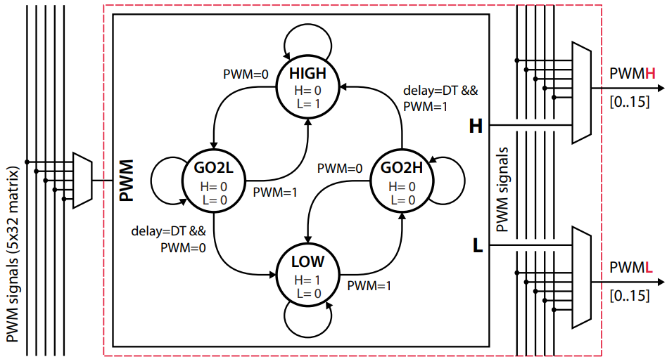
When the output mode is set as Dual (PWM_H + PWM_L) then a dead-time must be configured. The following figure taken from the B-Box datasheet shows the finite-state used to generate the complementary signals with dead-time.
Activate/deactivate parameter
Two conditions must be met for a signal to be outputted on a PWM output:
- The PWM outputs must be enabled. This condition is global to the system and can be controlled either from the Cockpit software or from the model using the Enable outputs block.
- The PWM outputs must be activated. The PWM outputs are activated by default but the user can choose to have an
activateinput signal to selectively activate or deactivate a PWM lane or channel during run-time.


