Table of Contents
The CAN_out block implements an output mailbox that supports sending messages using the CAN bus protocol. To receive messages, the CAN in block should be used instead. The supported CAN protocol variants are as follows:
- CAN 2.0A: standard format (11-bit identifier), up to 8 bytes payload
- CAN 2.0B: extended format (29-bit identifier), up to 8 bytes payload
- CAN FD: standard and extended format, up to 64 bytes payload
CAN 2.0A/B are supported on all imperix controllers, provided that the related hardware exists. However, CAN FD (flexible data) is only supported on the B-Box 4. The detailed compatibility list is shown below.
CANopen is a high-level protocol (OSI layer 7), which should not be confused with CAN (OSI layers 1 and 2). It is currently not supported on imperix equipment.
| Controller | Hardware resources | CAN 2.0A | CAN 2.0B | CAN FD |
|---|---|---|---|---|
| B-Box 4 | 2x channels (one RJ45 socket for each) Max. 5 Mbps (FD) | Yes | Yes | Yes |
| B-Box 3 (RCP) | 1x channel (one RJ45 socket) Max. 1 Mbps | Yes | Yes | No |
| B-Board 3 (PRO) | 1x channel (Tx/Rx pins or D-sub on EVM) Max. 1 Mbps | Yes | Yes | No |
| B-Box micro | N/A | No | No | No |
| TPI 8032 | 1x channel (two common RJ45 sockets) Max. 1 Mbps | Yes | Yes | No |
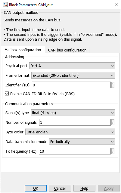
Parameters
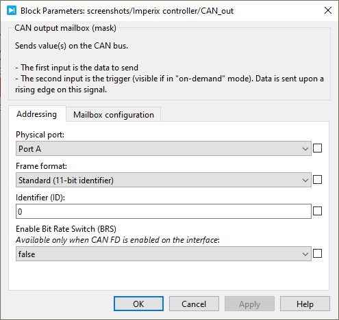
Addressing
- Physical port: selects the port on which the mailbox operate (Port A or Port B). Port B is only available on B-Box 4. For all the other devices, Port A must be selected.
- Frame format: selects between Standard (11-bit identifier) and Extended (29-bit identifier).
- Identifier (ID): sets the CAN identifier.
- Enable CAN FD Bit Rate Switch (BRS): Activates the CAN-FD extension to enable the communication at a higher data bitrate (see also CAN bus configuration below).
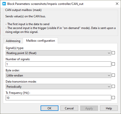
Communication parameters
- Signal(s) type: defines the data type accepted in the data input (int8, int16, int32, uint8, uint16, uint32, float32, or float64).
- Number of signals: specifies the vector size of the data to be sent.
- Byte order: defines the byte order in which the data will be sent. Either little-endian or big-endian.
- Data transmission mode: selects when the data is sent.
- On-demand: the user manually triggers the message transmissions.
- Periodically: the message is sent periodically, whether the data has been changed or not.
- Tx Frequency (Hz): sets the data transmission frequency when the Data transmission mode is set to Periodically.
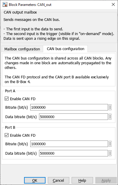
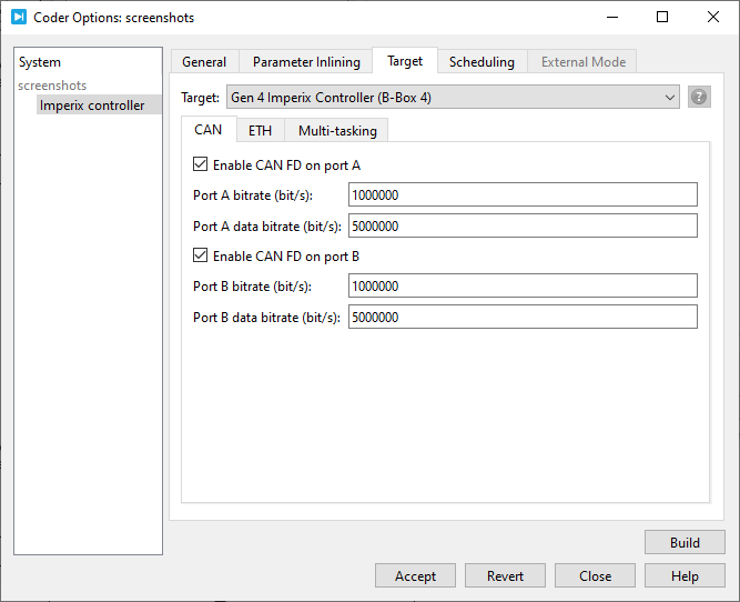
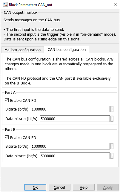
CAN bus configuration
In Simulink, the CAN bus configuration is performed from within the CAN block. In PLECS, the configuration is performed in the Target tab of Coder options windows (Coder -> Coder options, or Ctrl+Alt+B).
- The bitrate is the rate at which bits are transmitted on the bus (up to 1 Mbps),
- The data bitrate is the increased bitrate used to transmit the CAN FD frame payload when the Bit Rate Switch (BRS) is enabled (up to 5 Mbps).
Simulink block
Signal specification
- The data input signal supports a vector of data. The accepted data type is configured by Signal type parameter. The vector length can be configured with Number of signals parameter.
- The second input is the send data signal. It is used to initiate a data transmission when the on-demand mode has been selected. Data is sent upon a rising edge on this signal.
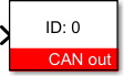
Mask
PLECS block
Signal specification
- The data input signal supports a vector of data. The accepted data type is configured by Signal type parameter. The vector length can be configured with Number of signals parameter.
- The second input is the send data signal. It is used to initiate a data transmission when the on-demand mode has been selected. Data is sent upon a rising edge on this signal.
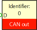
Mask