Table of Contents
The DAC block, or its equivalent C++ routines, is used to apply a given value to one of the Digital-to-Analog Converter (DAC) channels of the B-Box controllers. The table below summarizes the hardware specifications, including location, channel count, update rate, resolution, signalling, and output voltage range. Detailed information regarding DAC outputs is available in the associated product datasheet.
Comparative information about imperix’s programmable controllers is also given in PN250.
| Param. | B-Box 4 | B-Box 3 | B-Box micro | B-Board 3 |
|---|---|---|---|---|
| Location and count | 24x RJ45 ports | 4x SMA connector | Unavailable | Unavailable |
| Update rate | Up to 500 ksps | Up to 50 ksps | N/A | N/A |
| Resolution | 12 bits | 16 bits | N/A | N/A |
| Voltage range | ±10 V | ±5 V | N/A | N/A |
| Signalling | Differential | Single-ended | N/A | N/A |
| Product datasheet | B-Box 4 | B-Box 3 | B-Box micro | B-Board 3 |
Principle of operation
The DAC value is updated as soon as possible after the end of the CPU control task, with all DACs latching their outputs synchronously with a delay of up to one control task period.
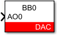
Simulink block
Signal specification
The input signal directly sets the analog output voltage, potentially clipping at the hardware limits: (±5V for B-Box 3, ±10V for B-Box 4).
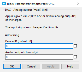
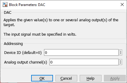
Standard parameters
Device IDselects which B-Box/B-Board to address when used in a multi-device configuration.Analog output channel(s)(vectorizable) selects a physical analog output channel.
PLECS block
Signal specification
The input signal sets the analog output voltage. The signal saturates at hardware limits: ±5V for B-Box RCP 3.0 and ±10V for B-Box 4.

Standard parameters
Device IDselects which B-Box/B-Board to address when used in a multi-device configuration.Analog output channel(s)(vectorizable) selects a physical analog output channel(s).