
Table of Contents
Modbus TCP is an industrial communication protocol used to exchange data between various automation devices. Originally developed for serial communication, it was later adapted for Ethernet networks as Modbus TCP. The original serial communication protocol is now referred to as Modbus RTU.
On imperix controllers, Modbus TCP is supported similarly to CAN(-FD) and UDP. It is mainly useful for non-time-critical data exchanges with third-party equipment. Modbus TCP is notably convenient when an imperix controller must interface with a Programmable Logic Controller (PLC), a Battery Management System (BMS), a Variable Frequency Drive (VFD), or metering and protection equipment. Other real-time communication protocols are also available, as presented in PN202.
This article explains when to use Modbus TCP with imperix controllers, summarizes the client/server communication model, and explains its implementation using mailboxes. The article also provides a complete example between a Modbus server running on a TPI8032 and an external client running Modbus Poll. The example is based on TN167 and implements a grid-following inverter that receives active and reactive power references from the Modbus client and returns selected measurements.
When to use Modbus TCP?
Data exchanges using Modbus TCP typically occur at an execution rate of 0.1-10Hz, with a maximum of 100Hz. This makes Modbus TCP suitable for supervision, monitoring, and setpoint exchanges. However, due to millisecond-scale latency and the absence of deterministic timing, Modbus TCP is generally inadequate for hard real-time control loops. Modbus TCP therefore fits best in applications where inter-device compatibility is more important than communication performance. In power electronics, this often corresponds to supervisory actions such as:
- Exchanging setpoints with other control-relevant devices;
- Reading measurements corresponding to slowly-varying dynamics (e.g. sun irradiance, motor speed, temperature, etc.);
- Transmitting status information to a SCADA system;
- Centralizing long-term logging data from a laboratory test bench.
How does Modbus TCP work?
Modbus operates on a client-server model: The client sends a request specifying a function code (which defines the action to perform, such as reading or writing data), a target address, and the relevant data. The server executes the requested action and returns the requested data or a confirmation that the write operation succeeded.
In Modbus-specific documentation, clients are also referred to as masters, while servers are designated as slaves.
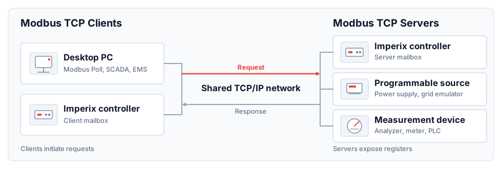
In Modbus TCP, the exchanges described above are encapsulated in standard TCP/IP packets and transmitted over Ethernet. Each message can carry up to 253 Bytes of Modbus payload. Addressing is based on IP, with four types of so-called data areas within each device. Each data area represents a distinct addressing space of 2^16 bits. These follow Modbus-specific naming conventions, reflecting the number of bits per register as well as the possible access types:
- Discrete inputs and discrete outputs are 1-bit registers. Discrete inputs are read-only, while discrete outputs are R/W accessible.
- Input registers and holding registers are 16-bit registers. Input registers are read-only, while holding registers are R/W accessible.
Modbus TCP support on imperix controllers
Imperix controllers support both Modbus master/client and Modbus slave/server. Similar to the other supported communication protocols, the concept of mailbox is used as a communication buffer separating control-related actions from communication-related ones. In practice, data is either read from or written to mailboxes during control interrupts and processed independently by the supervisor core (Linux).
The mailbox direction defines the data flow direction, regardless of the client/server mode. A Modbus_in mailbox receives data. Reciprocally, a Modbus_out mailbox exposes/sends data. The choice of the data area defines the access rules, as mentioned above.
Importantly, since Modbus uses 16-bit registers, 32-bit values commonly used on imperix controllers must be split across two registers. For this reason, endianness must always be configured consistently with the external client. This is also documented for both the input and output mailboxes.
Example: inverter supervision using Modbus TCP
The example implements a grid-connected inverter operating in grid-following mode, which injects controllable amounts of active and reactive power into the grid. This application is further presented in TN167.
On the communication side, the following configuration is implemented:
- The imperix controller, here a TPI8032, acts as a Modbus server.
- A Modbus client writes active and reactive power setpoints and reads selected measurements. For that, the Modbus Poll software is used to mimic the role of a PLC or strategy-level controller.
For convenience, this example only implements two mailboxes:
Modbus inreceives the active and reactive power references, here namedP_ref_GFandQ_ref_GF. It uses holding registers (16-bits, R/W-accessible). The corresponding address map is shown in Table 3.Modbus outexposes the measured active power, reactive power, and the grid angular frequency. It uses input registers (16-bits, read-only). The corresponding address map is shown in Table 4.
Here, since the user code employs 32-bit floating-point values, they occupy two consecutive 16-bit registers. It is also worth noting that, in a different application scenario, other data areas could be used as well, for instance if the non-imperix device requires it.
Writable setpoints
| Holding register range | Signal | Meaning |
| 0-1 | P_ref_GF | Active-power reference |
| 2-3 | Q_ref_GF | Reactive-power reference |
reactive-power setpoints.
Monitored values
| Input register range | Signal | Meaning |
| 0-1 | P_GFLI | Measured active power |
| 2-3 | Q_GFLI | Measured reactive power |
| 4-5 | w | Grid angular frequency |
The corresponding model is shown below in Fig. 2 and can be downloaded using the button below. General instructions for compiling, loading, and running generated user code are covered in PN138.
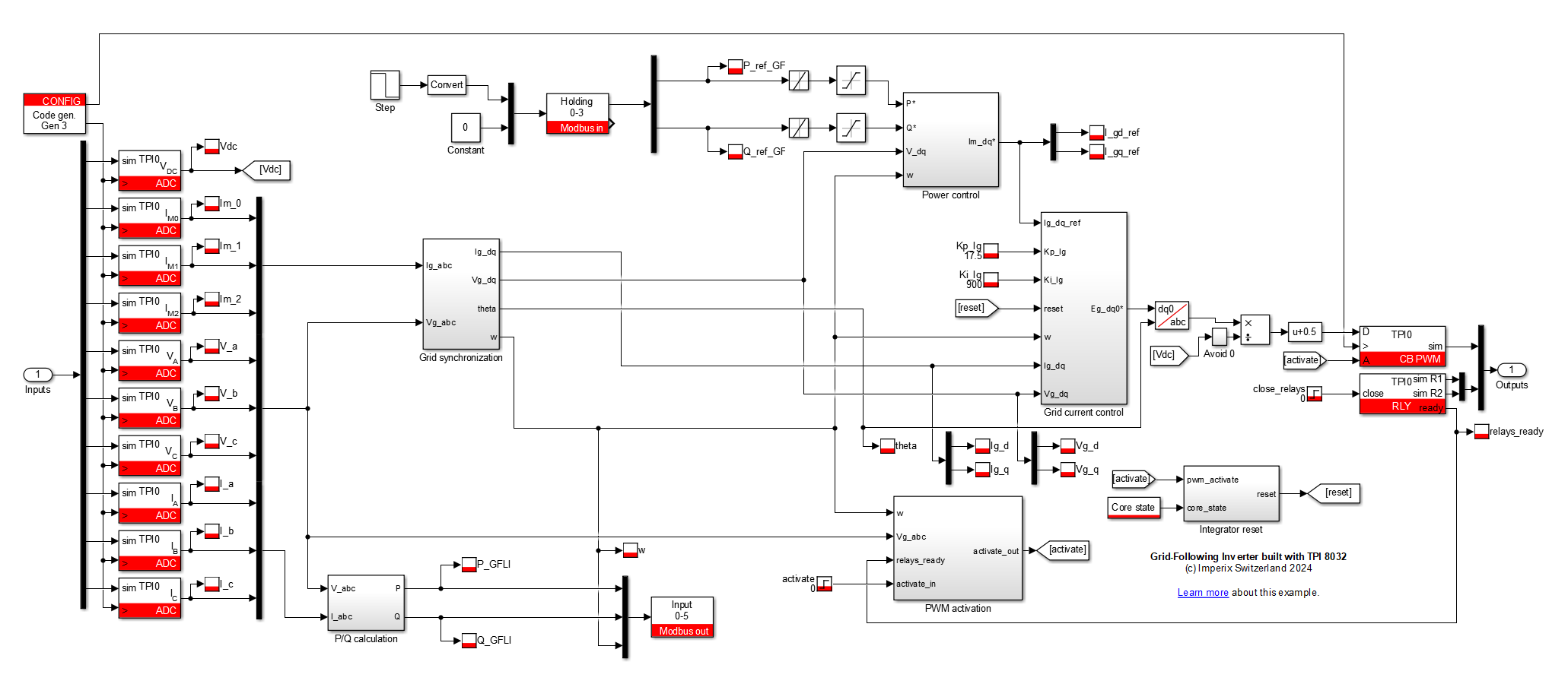
Configuration of the Modbus TCP mailboxes
The corresponding configuration of the mailboxes is shown below:
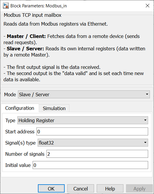
For the setpoints, the Modbus in mailbox is configured as a Holding register server because the external client must write into it. The mailbox then starts at address 0, receives two float32 values, and connects them to P_ref_GF and Q_ref_GF, matching Table 3. The data-valid output pin can be used to detect when the client has written a new value.
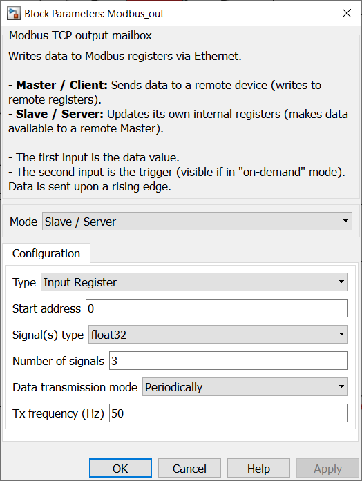
For the measurements, the Modbus out mailbox is configured as an Input register server because the external client only needs read access. The mailbox also starts at address 0 and exposes three float32 values, which occupy six input registers, as listed in Table 4.
Configuration of the client side
On the client side, Modbus Poll is used to simulate the behavior of the strategy-level controller that the inverter interacts with. This software is a commonly used tool for testing Modbus communication. It is particularly useful here because it offers advanced debugging features. Modbus Poll is a commercial software with a free evaluation version.
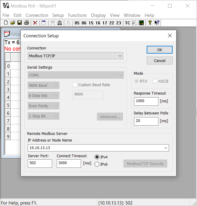
The software configuration begins by establishing a connection to the controller at its IP address and TCP port 502, as shown in Fig. 7.
Reading monitored values
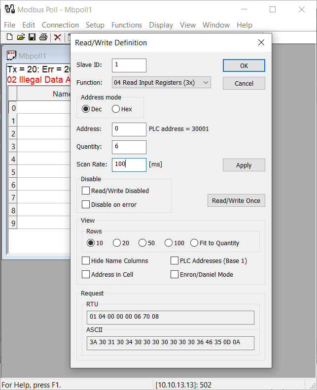
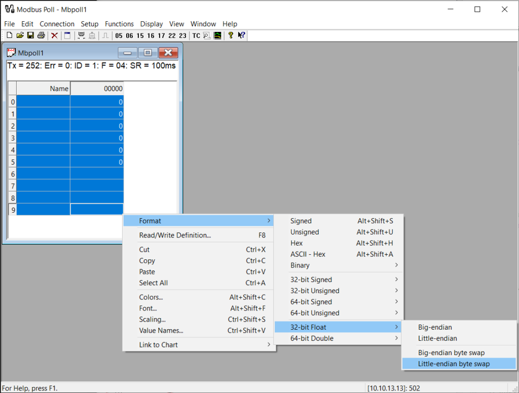
For reading the monitored values, the client is configured as shown in Table 5. The register cells are displayed as Little-endian byte swap so that each pair of 16-bit registers is decoded as one float32 value (see Fig. 9).
| Setting | Value | Comment |
| Unit ID | 1 | Conventional unit identifier used by Modbus Poll for this single-server test |
| Function | 04 Read Input Registers (3x) | The monitored values are exposed through the input-register data area |
| Address | 0 | The Modbus out mailbox starts at input register 0 |
| Quantity | 6 | The Modbus out mailbox starts at input register 0 |
| Scan rate | 100 ms | Polls at 10 Hz |
Writing setpoints
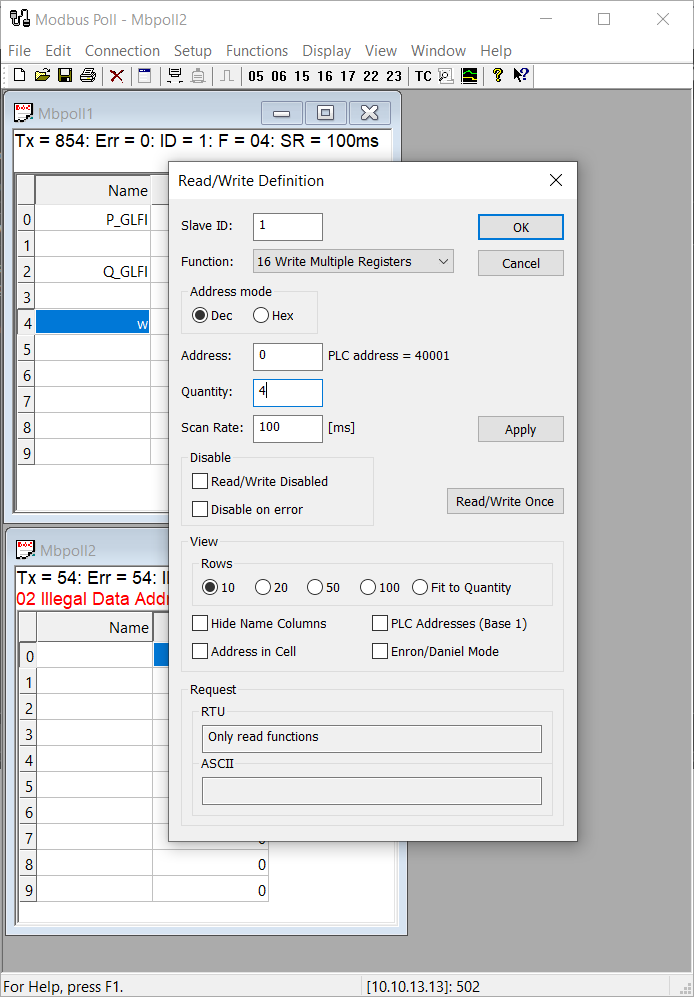
After that, a second Modbus Poll page is created (File > New) so that the read and write requests can be monitored simultaneously in the provided interface. The Holding register write definition is configured as shown in Table 6. The same display format (endianness) is also used here.
| Setting | Value | Comment |
| Unit ID | 1 | Same unit identifier as the read request |
| Function | 16 Write Multiple Registers | The two setpoints are writable holding-register values |
| Address | 0 | The Modbus in mailbox starts at holding register 0 |
| Quantity | 4 | Two float32 values occupy four 16-bit registers |
| Scan rate | 100 ms | Writes at 10 Hz, which is sufficient for manual setpoint changes |
Test scenario
For replicating this example, the user code must be first compiled and loaded on the target. The inverter controller and the PC running Modbus Poll must also be connected to the same Ethernet network.
At first, PWM outputs are left disabled and the proper reception of setpoints is checked. Once communication has been successfully tested, application-level tests can take place.
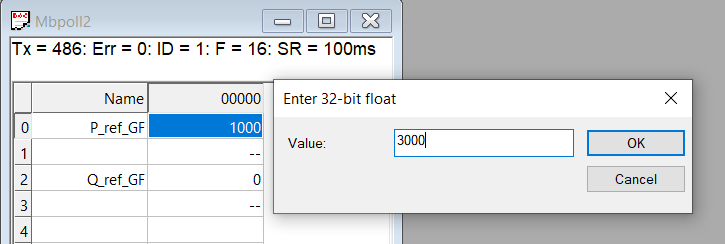
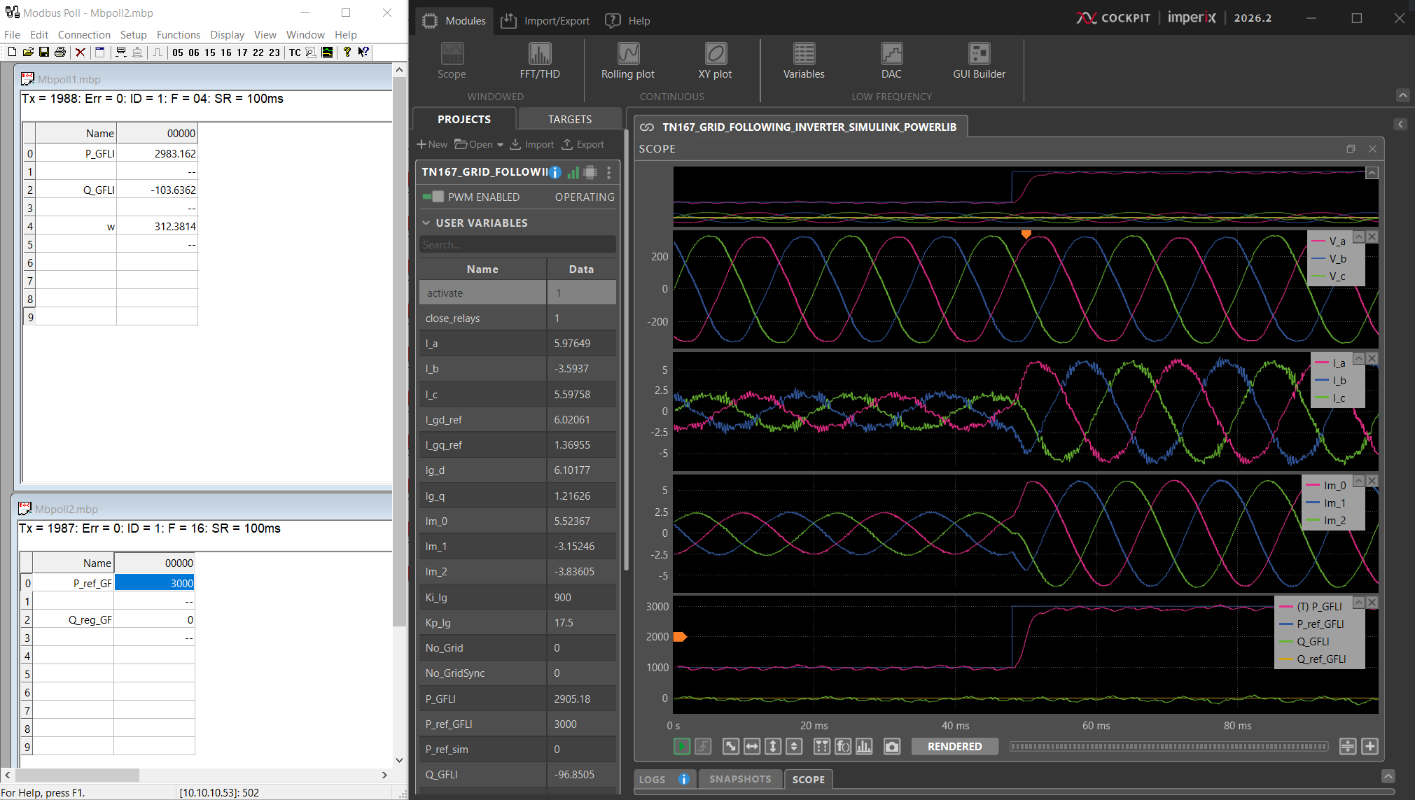
As shown in Figure 11, a reference step from 1000 Watts to 3000 Watts is executed, while the reactive-power reference remains at 0. The corresponding result is visible in the Cockpit screenshots shown in Figure 12.
 By Jules Perrin • August 6, 2026 • SD037
 By Nicolas Cherix • January 13, 2023 • PN202