Table of Contents
This article presents a Power Hardware-in-the-Loop (PHIL) system where the behavior of a Permanent Magnet Synchronous Machine (PMSM) is emulated for the validation of a physical motor drive. The proposed setup combines an imperix B-Box 4 and power modules with third-party real-time simulators.
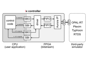
This page provides ready-to-use template projects for OPAL-RT, Plexim and Typhoon simulators, all of which leverage Aurora over the high-speed SFP communication link to exchange data between the imperix device and the simulator. More information about the implementation of the related drivers can be found in SFP communication drivers.
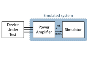
For a more detailed overview of PHIL testing with imperix, please refer to TN183. Another example illustrating the emulation of a microgrid is presented in TN184.
System description
The system architecture is illustrated below. The third-party simulator runs a model of a Permanent Magnet Synchronous Machine (PMSM) and its load. Conceptually, the power amplifier and drive are separate entities, each consisting of a dedicated B-Box 4 and three PEB-800-40 modules.
In practice, thanks to its high processing capacity and I/O count, a single B-Box 4 is used to execute both the power amplification and drive FOC control algorithms simultaneously, thereby minimizing required hardware.
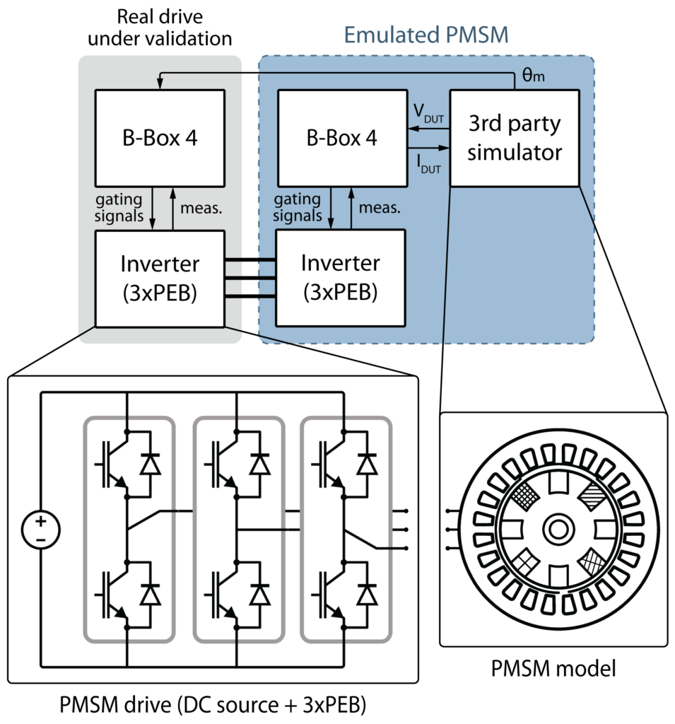 Conceptual system architecture, where the emulated system’s power amplifier and DUT have dedicated controllers.
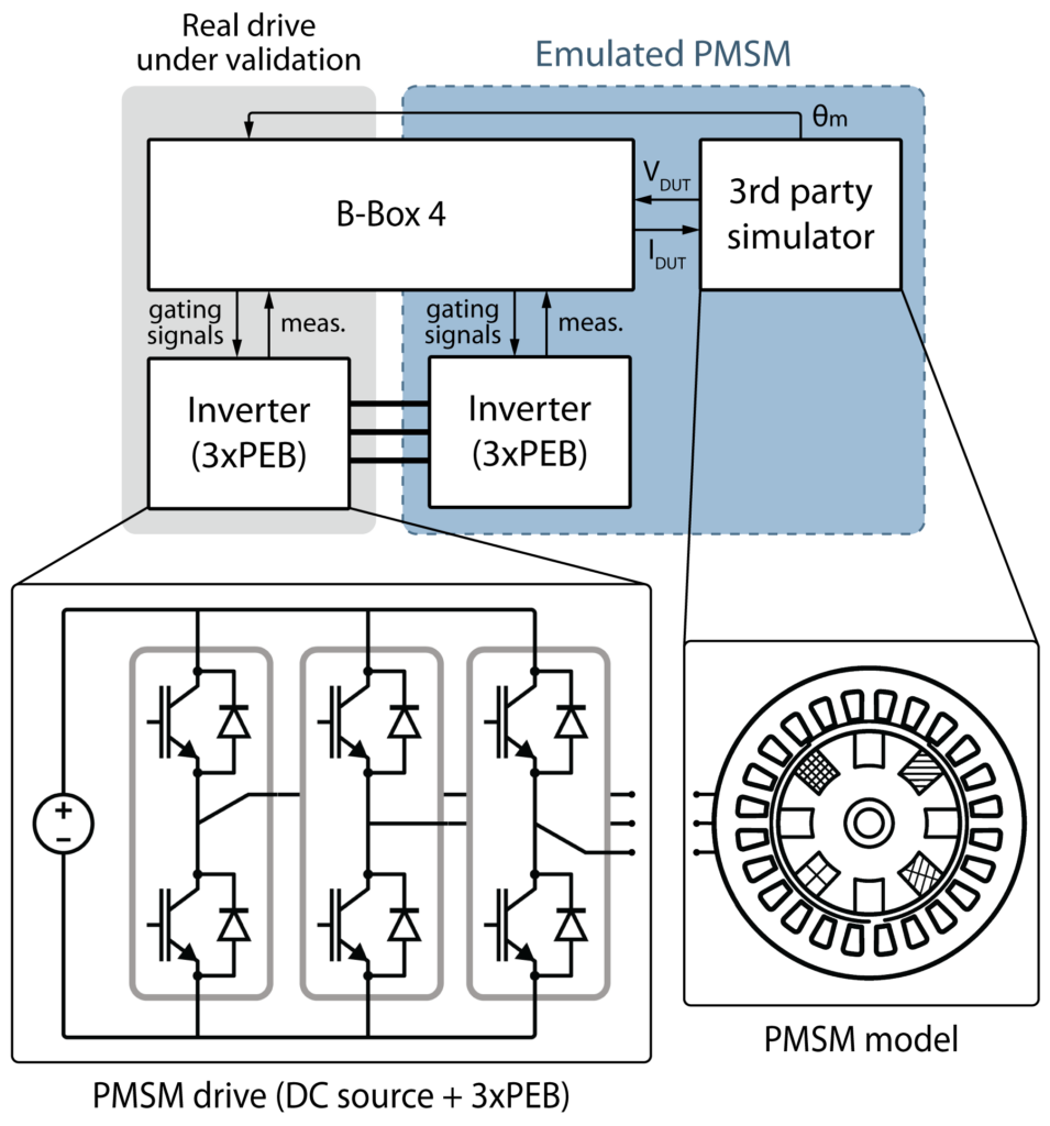 Simplified system architecture, where a single B-Box 4 controls both the emulated system’s power amplifier and the DUT power hardware.
Downloads
This example relies on three software components:
- The power amplifier and drive control model to be loaded onto the B-Box 4’s CPU.
- The vendor-specifc bitstream with Aurora drivers to be loaded onto the B-Box 4’s FPGA.
- The vendor-specific PMSM simulation model to be loaded onto the third-party simulator.
The list of supported devices is available here.
Power amplifier and drive model
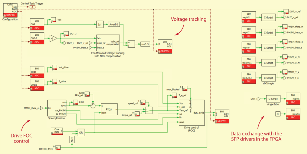
The B-Box 4 simultaneously runs the power amplifier control – essentially a voltage controller – and a motor drive control – here, a FOC method – for the drive under validation. The voltage tracking is a basic feedforward control with a compensation of the voltage drop on the inductors, while the FOC control is directly inspired by TN111.
Both algorithms are gathered within one single PLECS model. Once built, this model must be loaded onto the B-Box 4’s CPU via Cockpit.
Bitstream with Aurora drivers
In this example , the B-Box 4 and the simulator communicate over SFP, which requires Aurora drivers specifically designed for the targeted third-party simulator. A template Vivado project with appropriate drivers is provided for each vendor in the table below.
To generate the bitstream, download the bitstream generation scripts from the table below and follow the step-by-step bitstream generation procedure. Once generated, load the bitstream onto the B-Box 4’s FPGA via Cockpit.
For interested readers, the related pages provide explanations about the provided drivers.
| Vendor | Bitstream generation scripts | Related page |
| OPAL-RT | aurora_ix_opalrt_gen_scripts.zip | Aurora link with OPAL-RT via SFP |
| Plexim | aurora_ix_plexim_gen_scripts.zip | Aurora link with Plexim via SFP |
| Typhoon | aurora_ix_typhoon_gen_scripts.zip | Aurora link with Typhoon via SFP |
PMSM simulation files
The PMSM model has been implemented for each considered vendor. The files are available in the table below.
| Vendor | Microgrid model |
| OPAL-RT | phil_pmsm_ix_opalrt_rtlab.zip |
| Plexim | phil_pmsm_ix_plexim_rtbox.plecs |
| Typhoon | phil_pmsm_ix_typhoon_files.zip |
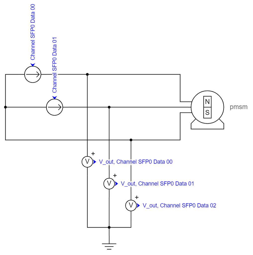
OPAL-RT Schematic Editor
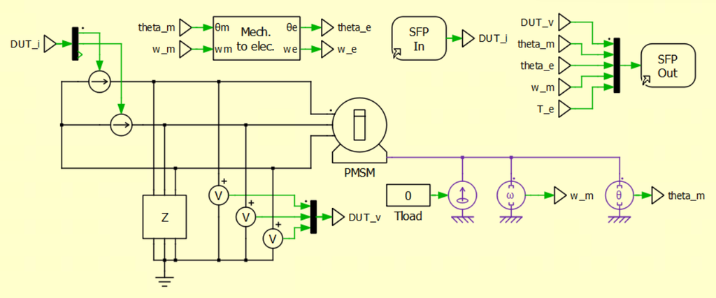
Plexim PLECS environment
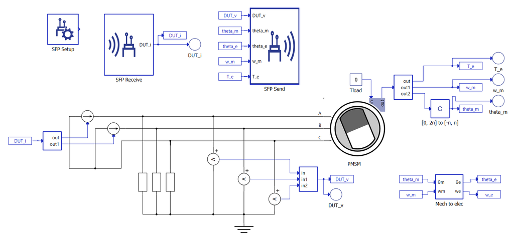
Typhoon Schematic Editor
Experimental validation
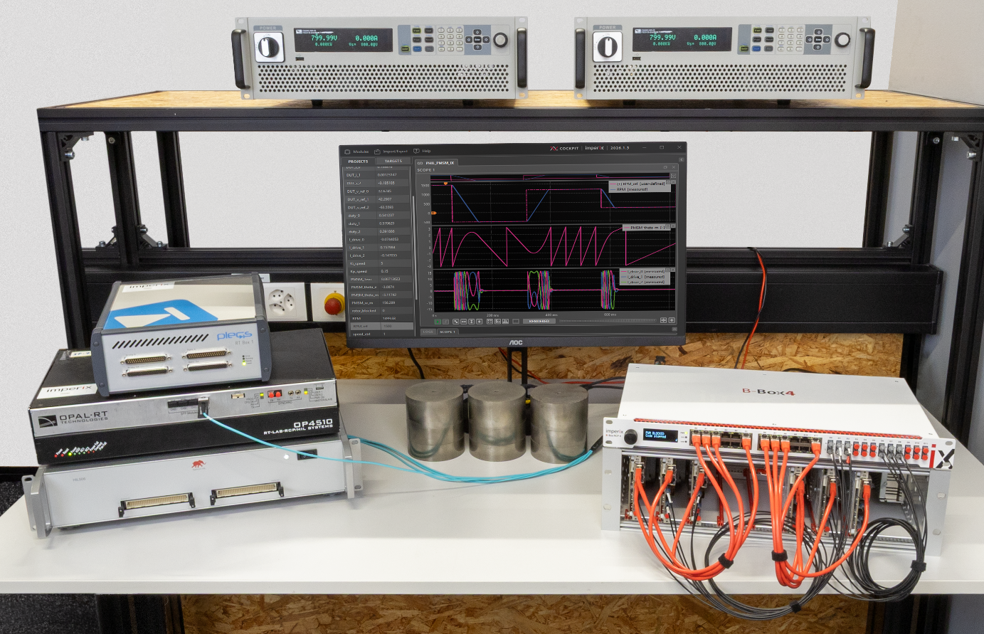
The lab setup is depicted below. As detailed in the system description, it consists of an imperix B-Box 4 controlling six PEB-800-40 modules forming two three-phase inverters. The B-Box 4 is directly connected to a third-party simulator via SFP. Coupling inductors are placed between both inverters.
Results
This section exposes the experimental results collected during laboratory validation. While these measurements were acquired using an RT-Box 1, equivalent results were obtained with an OPAL-RT OP4510 and a Typhoon HIL506. The presented figures highlight the drive control perspective.
Thanks to the high-speed SFP communication between the TPI and the simulator, additional simulation variables – such as the PMSM electromechanical torque (PMSM_Tem) – can be transmitted and monitored directly from Cockpit.
Speed profile
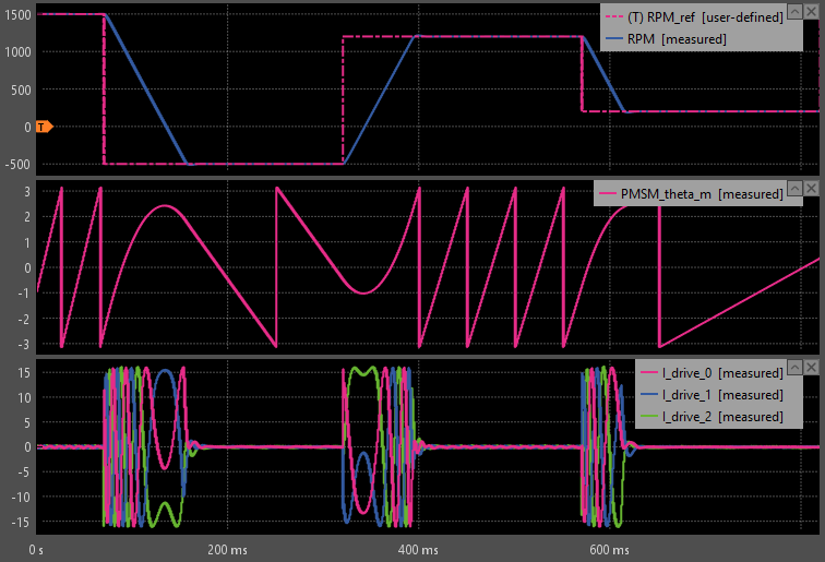
In the following figure, a reference speed profile is fed to the drive controller. As shown, the speed profile is well followed. The angle variation is consistent with the speed profile, particularly during speed reversals.
The maximum acceleration of the PMSM is bounded by the maximum torque specified in the drive FOC control to limit the current flowing in the inverter branches.
profile to the drive controller (Cockpit software)
Load torque step
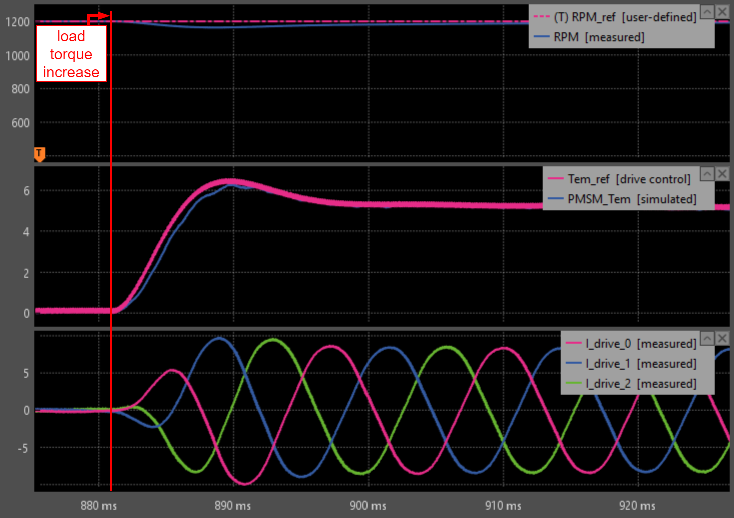
In the figure below, a load torque step from 0 to 5 Nm is applied in the simulation model during runtime.
As expected, this change leads to a slight decrease of the motor’s speed, pushing the drive control to increase its internal electromagnetic torque reference (Tem_ref) and output currents (I_drive). This increase of currents amplitude is captured by the simulation, as verified by the PMSM_Tem variable – extracted from the simulation model – that closely follows the Tem_ref variable from the drive control.
in the simulation during runtime (Cockpit software)
The presented results confirm that, from the drive’s perspective, the emulated system behaves in the same way as a real motor.
 By François Ledent • September 29, 2026 • TN184