
Table of Contents
This note addresses the implementation of CPU-based multi-rate control on imperix controllers, supported by both the ACG SDK (for Simulink and PLECS environments) and the CPP SDK. The article focuses on general principles, while environment-specific configuration instructions are provided separately for Simulink (PN145), PLECS (PN155), and C++ (PN149).
In this article, multi-rate control involves control tasks running on the CPU, focusing on lower-priority tasks that run slower than the main control rate. That said, multi-rate control is also possible by leveraging both the CPU and the FPGA simultaneously, which is typically useful for running faster tasks on the FPGA. TN147 shows the achievable performance thanks to FPGA-based control.
Context
Controlling power electronic systems involves processes with physical phenomena operating across vastly different time scales. For instance, a grid-tied solar inverter control structure implies a fast current control loop (typically 10–50 kHz), a slower DC-link voltage control (typically 100–1000 Hz), and a much slower MPPT algorithm (typically 1–10 Hz). Because controlling slow physical processes does not require high sampling or control execution rates, controller resources can be saved by matching sampling and execution rates to the underlying dynamics of each process.
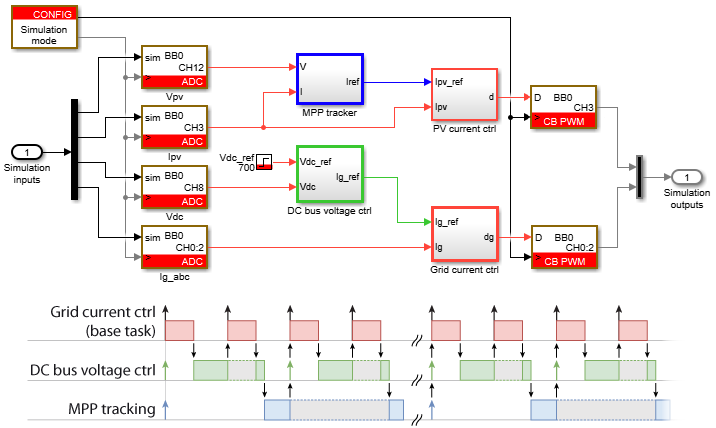
For example, the diagram below illustrates the control structure of a grid-tied PV inverter (adapted from AN006 for illustration purposes). The different colors of the control blocks represent distinct execution rates, using Simulink’s discrete sample-time visualization.
Multi-rate scheduling approaches
In a multirate control system, a rate defines the required execution frequency of a control algorithm, while a task defines the execution context in which one or more rates are scheduled. These rates must then be mapped to an appropriate task structure.
Two fundamental scheduling approaches can be used: single-tasking and multitasking. The following sections describe their operating principles and compare their characteristics.
Imperix controllers support both execution modes. Dedicated configuration guidelines for single-tasking and multitasking on imperix controllers are provided separately for Simulink (PN145), PLECS (PN155), and C++ (PN149).
Single-tasking approach
In a single-tasking configuration, all execution rates are scheduled into a single monolithic control task. To derive secondary execution rates from the base rate, the generated source code uses software counters to trigger the slower routines.
Simulink or PLECS automatically schedules the slower routines based on signal sample times. Alternatively, the user can define scheduling explicitly using mechanisms such as triggered subsystems.
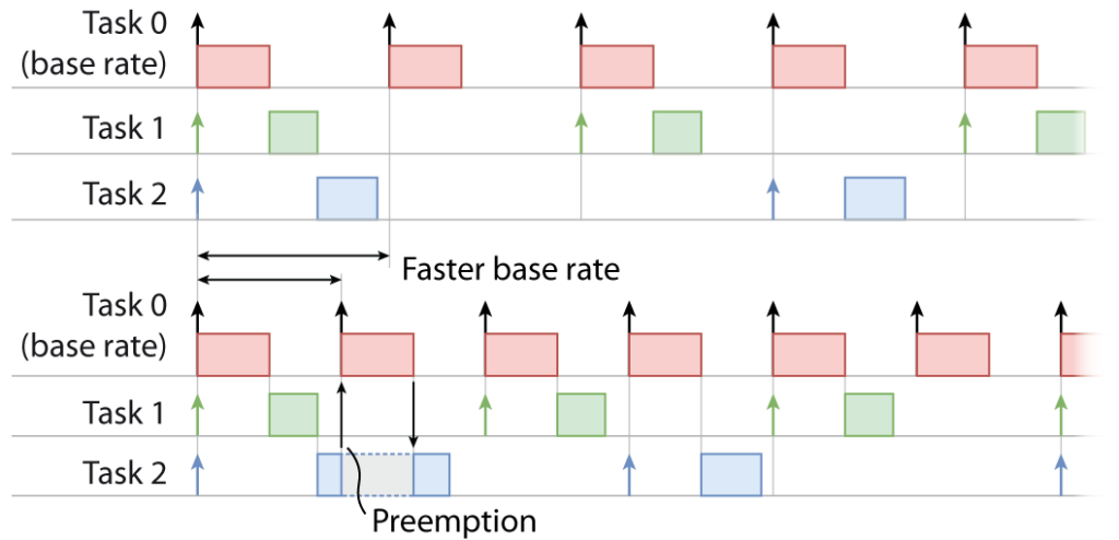
Because all subroutines run within a unique base-rate task, they execute sequentially. This sequential execution represents the primary limitation of single-tasking: the base-rate period must be long enough to accommodate the combined worst-case execution time of all overlapping subroutines (as illustrated in the figure below). Consequently, this constraint limits the maximum achievable base-rate frequency and prevents optimal utilization of the available computational resources.

Multitasking approach
In a multitasking configuration, although the control algorithm runs on a single CPU, the system assigns different execution rates to distinct, prioritized tasks. Higher-priority tasks can interrupt lower-priority tasks through a mechanism known as preemption.
Similar to the single-tasking approach, the base rate remains the fundamental timing reference for scheduling tasks. However, lower-priority tasks are no longer required to complete within a single base-rate period. If a slow (lower-priority) task is still running when a high-priority base-rate interrupt occurs, the faster task preempts it. The slower task then resumes execution once the higher-priority task completes. This approach makes it possible to achieve a higher base-rate frequency or run more resource-intensive slow tasks without violating real-time execution constraints.
The figure below illustrates task preemption and shows how multitasking enables a higher base rate than single-tasking.
Data exchange and data dependency
In a multitasking environment, task execution is separated, but all tasks run on the same physical processor and share a single global memory space. Since tasks run at different execution rates, they can read and write shared data asynchronously. If data exchange is not handled properly and a higher-priority task preempts a lower-priority task mid-execution, it may read partially updated data or overwrite variables before the slower task finishes processing them.
To prevent data corruption, Simulink and PLECS provide a Rate Transition block to ensure time-consistent inter-task data transfers. More information about rate transition is given in Multi-rate control on Simulink (PN145) and Multi-rate control on PLECS (PN155). C++ users should consider appropriate data-synchronization mechanisms, such as double buffering.
Execution determinism
Because higher-priority tasks can preempt lower-priority tasks, multitasking execution may introduce execution-time jitter on lower-priority tasks. In most power electronics applications, this is not an issue because time-critical inner control loops run at the highest priority and therefore have deterministic timing. Lower-priority tasks, such as outer control loops, supervisory algorithms, or communication, generally tolerate the small timing variations introduced by preemption. Nevertheless, avoid assigning time-critical algorithms to lower-priority tasks. If all rates require deterministic execution, prefer single-tasking.
Comparison of approaches
The table below summarizes the key architectural differences and trade-offs between the single-tasking and multitasking approaches.
| Param. | Single-tasking | Multitasking |
|---|---|---|
| Generated code structure | Single function | Tasks separated into multiple functions |
| Task preemption | No | Yes |
| Non-periodic task execution | Yes, with triggered subsystems | No |
| Execution constraint | More restrictive: The base-rate period must be longer than all overlapping tasks combined | Less restrictive: Each task’s execution time must fit within its own period |
| Data integrity | Intrinsically avoids data corruption during exchanges between different rates | Requires rate-transition blocks to avoid data corruption during exchanges between different rates |
| Execution period determinism | Yes | Only base-rate task |
Multitasking on imperix controllers
Task execution rules
As detailed in Operating principles of imperix controllers, and mentioned above, the control algorithm relies on an interrupt-based architecture. A hardware interrupt schedules the main control task (base-rate task), and subsequent tasks are triggered via software interrupts immediately after the main task completes. This operation follows the following concepts:
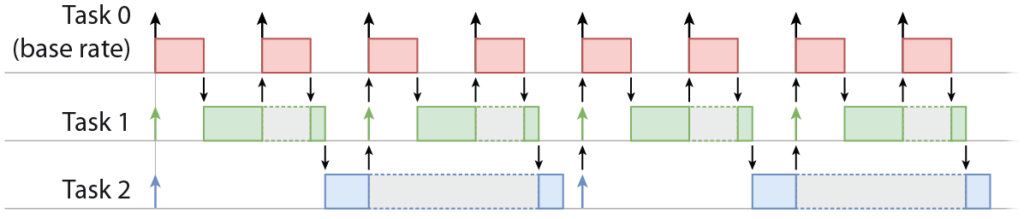
- Rate-monotonic preemption: Tasks use priority-based preemption. The system automatically assigns higher priority to higher-frequency tasks (see figure below).
- Overrun detection: An overrun occurs when a task fails to finish before its next scheduled execution time. Task overruns are strictly forbidden and will trigger a protection trip that disables all PWM outputs (core state: FAULT)
- Software interrupt limit: The architecture supports up to 8 concurrent software interrupts.
- CPU load visibility: The CPU load metric displayed in Cockpit (Timings info tab) reflects only the main control task.
Control delay of sub-rate tasks
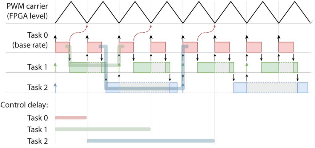
The evaluation of the control delay for loops running in the base-rate task is detailed in Discrete control delay identification. When control loops are implemented in slower tasks within a multitasking configuration, their control delay can increase and/or vary due to task preemption. Furthermore, to evaluate the control delay of these slower tasks, it is crucial to account for the fact that data exchange with the controller’s peripheral hardware (ADC, PWM, GPI, GPO, etc.) must pass through the base-rate task.
The figure below illustrates the data paths through lower-priority tasks. The control delay for a given task is the elapsed time between the sampling event (whose latest data the base-rate task processes first) and the moment the updated parameters (typically PWM duty cycles) are applied at the hardware modulator level. The resulting control delays for each task are also illustrated below.
Further readings
Environment-specific configuration instructions are provided separately for the following programming environments:
Related Articles
Discrete control delay identification

Maximum Power Point Tracking (MPPT) algorithms

Multi-rate control on PLECS with ACG SDK

Multi-rate control on Simulink with ACG SDK

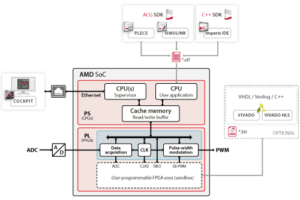
Operating principles of imperix controllers

Three-phase PV inverter for grid-tied applications
