Table of Contents
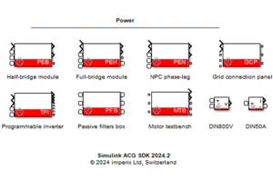
The PFB block is a simulation model included in the Imperix Power library. It models one symmetrical half of the imperix passive filters box in Simulink and PLECS simulation.
For more information regarding the Imperix Power library, please read Getting started with Imperix Power library.
• ACG SDK 2024.2: First release. Support for PLECS and Simulink SPS library (“Black” blocks).
• ACG SDK 2025.2: Addition of thermal models for most PEB and PEN modules.
• ACG SDK 2026.1: Support for the latest products (PEB-800-40, VSR-1000-ISO, VSR-500-HBW, CSR-25-HBW).
• ACG SDK 2026.1.3: Support for Simulink Simscape Electrical library (“Blue” blocks).
• Simulink (R2016a or newer): Simscape is required.
• Plexim PLECS (4.5 or newer): No particular requirement.
Additionally, for Simulink:
• Simscape Electrical library: Simscape Electrical is required.
• SPS library: Simscape Specialized Power Systems (up to R2025b) or OPAL-RT SPS Software is required.
Modeling of PFB
The PFB model has two modeling levels:
- (A) Simple
- (B) Detailed
As introduced in the datasheet, the passive filter box consists of 3-phase power inductors, feedback capacitors, and an EMC filter. The power circuits can be wired differently for flexible use in power applications. According to all the possible wiring situations, the PFB model offers 3 wiring configurations:
- Inductors: only the power inductors are used.
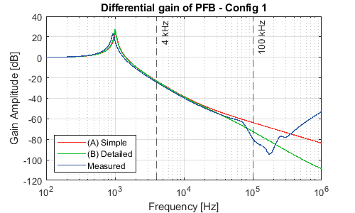
- Inductors, Cf/Rf, EMC filter: refer to the “transformer-less connection to the grid” example in the datasheet. This option is named “config 1” in the later analysis.
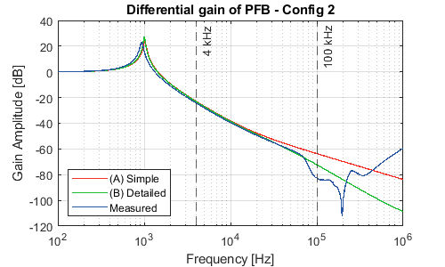
- Inductors, EMC filter, Cf/Rf: refer to the “connection to the grid with an isolation transformer” example in the datasheet. This option is named “config 2” in the later analysis.
For more detailed model parameters and measurement results, please contact [email protected].
Power inductors
The power inductors are modeled by the inductance \(L_m\) and equivalent series resistance (ESR)\(R_m\), which is the same for all the modeling levels. The impedance of the main inductors versus measured results is shown below.
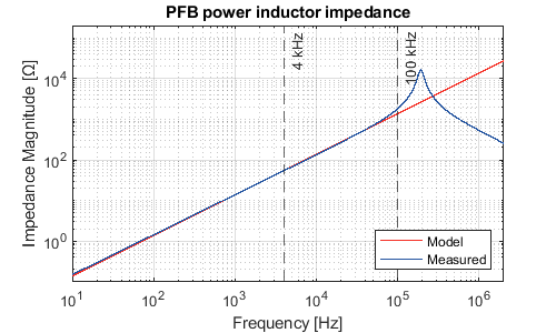
| Lm [mH] | 2.2 |
| Rm [mΩ] | 29 |
EMC filter
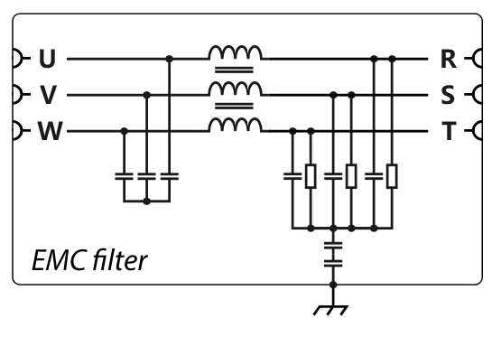
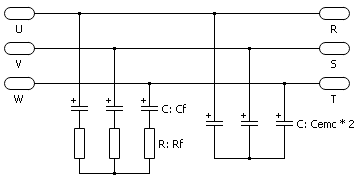
The figure below shows the schematic of the EMC filter. It has one common mode inductor and 2 three-phase capacitors on both sides of the inductor.
Since the common-mode characteristics mostly lie in the high-frequency range of up to hundreds of kilohertz to megahertz, only the differential mode is considered in the PFB model. The common mode path to GND is removed from the model. Furthermore, the leakage inductance of the common mode inductor can be neglected, and the capacitors can be lumped into one 3-phase capacitor. The schematic of the EMC filter model is shown below.
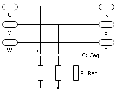
In the differential mode, the combination of the EMC filter and the power inductors forms an LC circuit between phases. The model’s accuracy can be validated by comparing the transfer function of the LC circuit with the measurement results. The comparison and parameters are displayed below.
| Req [Ω] | 0.6 |
| Ceq [μF] | 16.6 |
| Rf [Ω] | 1 |
| Cf [μF] | 10 |
| Cemc [μF] | 3.3 |
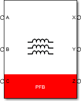
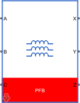
Simulink PFB block
Port specification
- The connection ports
A,B,Care the electrical ports connected to the physical portsA,B,Con the box. - The connection ports
X,Y,Zare the electrical ports connected to the physical portsX,Y,Zon the box. - The connection ports
R,S,Tare the electrical ports connected to the physical portsR,S,Ton the box. - The connection ports
U,V,Ware the electrical ports connected to the physical portsU,V,Won the box.
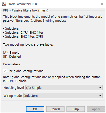
Parameters
Use global configurationsis ticked when the block receives global configurations from theConfigblock.Modeling levelselects the modeling level.Wiring configurationselects the wiring configuration.
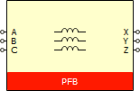
PLECS PFB block
Port specification
- The connection ports
A,B,Care the electrical ports connected to the physical portsA,B,Con the box. - The connection ports
X,Y,Zare the electrical ports connected to the physical portsX,Y,Zon the box. - The connection ports
R,S,Tare the electrical ports connected to the physical portsR,S,Ton the box. - The connection ports
U,V,Ware the electrical ports connected to the physical portsU,V,Won the box.
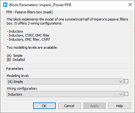
Parameters
Modeling levelselects the modeling level.Wiring configurationselects the wiring configuration.
Probe signals
This block has no signals to be monitored.