Table of Contents
What is an onboard battery charger?
An onboard battery charger (OBC) is an automotive power electronic converter tailored to charge an EV directly from the grid. As the name suggests, the onboard battery charger is integrated into the vehicle and remains with it at all times. As a result, researchers and Original Equipment Manufacturers (OEMs) continually innovate to ensure that OBCs become lighter and more efficient. OBCs with high power density enable faster charging time, more compact designs, and improved efficiency. Therefore, a light onboard battery charger increases the range of an electric vehicle. This reduces the overall cost per mile for an EV driver.
While DC fast charging is an alternative to charging an EV using an OBC (see AN007 – Fast electric vehicle charger with intermediate energy storage for an example), the convenience of charging the vehicle from the much more accessible (including at home) AC grid is not to be underestimated.
Onboard battery charger design example
Design and control objectives
The following are the primary design and control objectives for the onboard charger:
- An OBC must be able to control the battery charging current/voltage
- An OBC must be able to maintain a unity power factor when charging the battery
- For safety and to reduce the common-mode voltage, an OBC should be isolated from the grid
- It should have high power density and ideally light weight
In addition to the 4 core objectives, if the onboard battery charger is able to operate bidirectionally, it opens the door for vehicle-to-grid (V2G) or vehicle-to-home (V2H) applications as well, but this feature has not seen widespread implementation as bi-directional designs may increase the size and cost of OBCs.
When considering objectives 1 and 2 from the list above, a common solution is to consider two-stage converters, which simplify the decoupling of the two distinct controlled variables, namely the battery charge current and the power factor from the grid [1].
Similarly, when considering objectives 3 and 4 from the list above, the design of the onboard battery charger is constrained to high-frequency isolation transformers because the weight and volume of a transformer are inversely proportional to its operating frequency. High-frequency transformers are common in isolated DC/DC converters, resulting in most onboard battery chargers having a non-isolated active rectification stage and an isolated DC/DC battery charging stage [1].
Typical topology
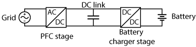
The two-stage approach shown in Figure 1 is a common configuration for onboard battery chargers. Multiple converter topologies can be implemented to achieve the control objectives of each stage, and the choice made depends on multiple factors such as controllability, manufacturing cost, targeted efficiency, etc.
Some examples are listed below:
PFC stage
- Boost PFC converter
- Bridgeless dual-boost PFC converter
- totem-pole PFC converter
Battery charger stage
- LLC converter
- DAB converter
- Full bridge converter
In addition, the choice between implementing a three-phase onboard battery charger (max 22 kW charging) and a single-phase version (max 7.4 kW charging) also affects topology selection. This article focuses on the single-phase implementation of the OBC, as phase shedding [2] in 3-phase OBCs means that single-phase control strategies are also relevant for three-phase converters.
Onboard battery charger control strategy
The control strategy can be divided into two parts as follows:
Power factor correction
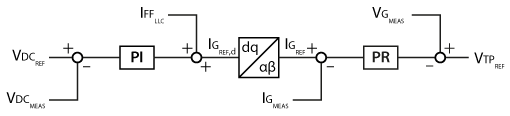
The power factor controller, shown in Figure 2, is a 2-stage cascaded controller based on the control from TN113 – Single-phase totem-pole PFC rectifier. The inner loop controls the grid current using a PR controller, and the outer loop controls the DC bus voltage using a PI controller. In addition, the feed-forward of the charging current is added to the output of the DC bus voltage controller to reduce the DC bus voltage deviation, improving controller performance.
Due to the nature of the single-phase grid connection, a 100 Hz (or twice the grid frequency) power ripple is inevitable, as no power from the grid can be transferred during the instances where the grid voltage is equal to zero. To ensure that the outer loop does not attempt to correct this ripple, its bandwidth must be reduced to below 100 Hz.
Battery charger control
Compared to the rating of EV batteries, many onboard battery chargers charge the traction battery at a relatively low C-rate. Because of this, the charge current is limited either from the grid connection or the rating of the OBC itself. The charge current can therefore be set constant to the maximum rated current. At higher state-of-charges, the traditional technique is to charge using constant voltage to ensure that the battery is not overcharged [3]. It is noteworthy that research on batteries is constantly evolving, and the charging technique mentioned above is only one of many possible techniques that can be implemented [3].
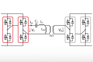
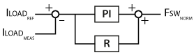
Furthermore, due to the long charging duration for EV batteries, the dynamics of the current tracking are less relevant compared to the rejection of the 100Hz ripple on the DC bus. Therefore, the control implemented in this section, shown in Figure 3, is an extension of the control implemented in TN126 – LLC resonant converter for battery charging applications. Along with the PI controller, a resonant controller is added in parallel to better reject the 100 Hz ripple.
The kr gain must be tuned conservatively to ensure stability as it is a linear controller acting on a non-linear plant (similar to the PI gains discussed in TN126). This is why the 100 Hz ripple cannot be completely eliminated by this control method.
Realization of an onboard battery charger using imperix products
System setup
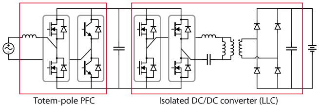
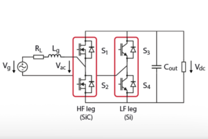
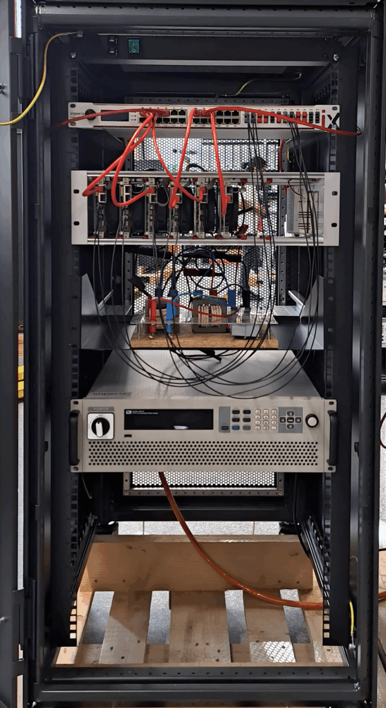
The topology considered for the practical demonstration of the onboard battery charger, shown in Figure 4, is a totem-pole active rectifier in series with an LLC series resonant converter. The only non-standard component utilized in the commissioning of this system is the custom resonant tank for the LLC converter. Additional details about it can be found in TN127 – Tank circuit design for an LLC resonant converter. The system is assembled in a standard 19″ server cabinet and is shown in the figure below.
Standard component list
- 1x B-Box 4, used as programmable controller
- 1x 2.2mH inductor, found in Passive Filters Box
- 1x AC grid panel 230 V
- 1x reversible DC power supply, used as a battery emulator at the output, with a configurable voltage
- 1x VSR-1000-ISO voltage sensor, to measure the grid voltage
- 1x CSR-25-HBW current sensor, to measure the output current
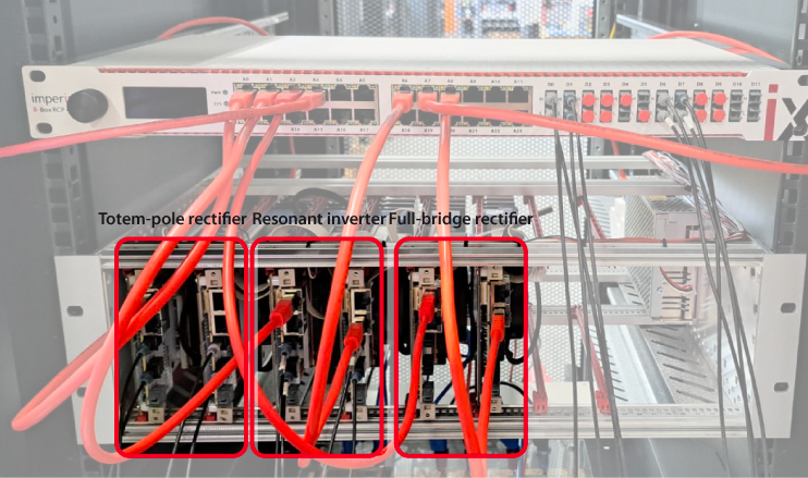
To simplify the experiment, only one type of imperix power module, i.e., PEB 800-40, is used as shown in Figure 6, although varying conditions are expected to be experienced by each power module, for each part of the OBC.
- x2 PEB 800-40, used for the high-frequency and low-frequency leg of the totem-pole rectifier
- 2x PEB 800-40, used to create a high-frequency SiC H-bridge
- 2x PEB 800-40, used without any gate signals as a rectifier for the transformer current
In order to maintain safety in the laboratory alongside the flexibility, it is suggested that the advice in the following article is followed: Safety recommendations for working in the lab.
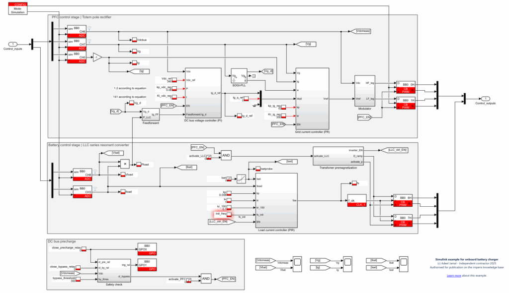
Control implementation in Simulink
The control strategy described in section 2.3 can easily be implemented on the B-Box 4 using Simulink with the ACG SDK. The model shown in the figure below can be downloaded and run both offline and on the physical controller.
Experimental results
The results in this section are limited to a specific battery voltage and are obtained by emulating the battery with the reversible DC power supply set to 400 V.
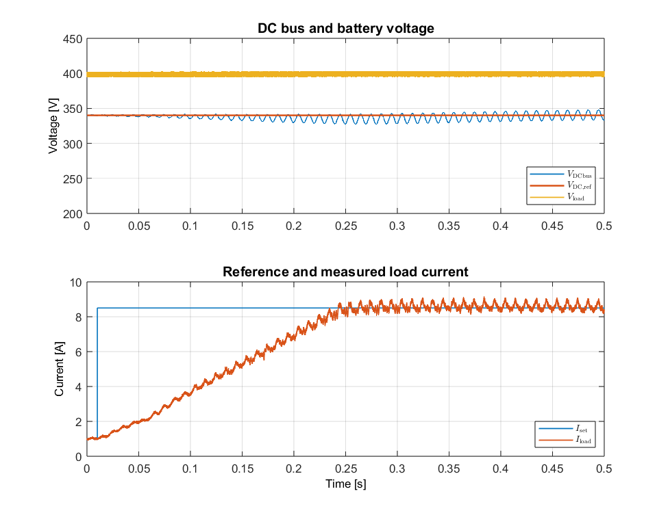
Figure 8 shows the grid voltage and current. The power factor of the onboard battery charger is 0.99 with around 1.8% THD.
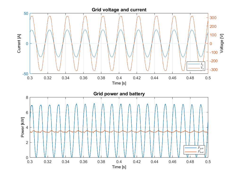
Power ripple from a single-phase system is inevitable, and energy storage is required to mitigate its effects. Figure 9 demonstrates that despite the power ripple due to a single-phase connection to the grid, the energy stored in the DC bus allows for constant current charging of the battery.
Figure 10 illustrates the 100 Hz DC bus voltage ripple rejection of the LLC converter using the control strategy described in section 2.3.2. While the DC bus voltage ripple increases proportionally to the load current, the non-linear transfer function of the LLC stage results in the ripple rejection varying non-linearly with the load current.
When Iset is equal to 8.5 A, the voltage ripple in the DC bus voltage is 14.2 Vpp, and the current ripple is 0.85 A.
References
[1] A. Khaligh and M. D’Antonio, “Global Trends in High-Power On-Board Chargers for Electric Vehicles,” in IEEE Transactions on Vehicular Technology, April 2019
[2] C. Wang, M. Xu, F. C. Lee and Z. Luo, “Light load efficiency improvement for multi-channel PFC,” in Proc. of PESC, Rhodes, Greece, 2008
[3] W. Shen, T. Tu Vo and A. Kapoor, “Charging algorithms of lithium-ion batteries: An overview,” in Proc. of ICIEA, Singapore, 2012