Table of Contents
This article provides essential information for developing power converters using the PEB-800-40 module. It is intended to guide first-time users through the safe and successful construction of power electronics prototypes, offering a clear and structured path for integrating the module into laboratory activities.
The documentation follows a logical implementation sequence, beginning with a functional overview and mechanical assembly requirements. Subsequent sections detail critical system protections, sensor configuration protocols, and provide practical application examples.
Functional overview
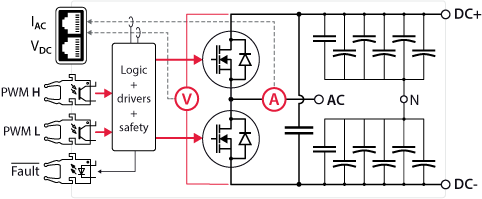
The PEB-800-40 power module is constructed with a half-bridge switching cell utilizing two SiC semiconductors. It further incorporates all the necessary components for the rapid implementation of laboratory prototypes, namely:
- Isolated gate drivers
- Isolated DC bus voltage and phase-leg current sensors
- DC bus capacitors with discharge circuit
- Protection mechanisms against over-voltage / current / temperature and 1-1 gating signals
- A speed-regulated cooling solution
An external controller (e.g. the B-Box 4) is necessary for running control algorithms and generating PWM signals. It can also retrieve the on-board measurements, permitting system monitoring and closed-loop control.
Mechanical assembly
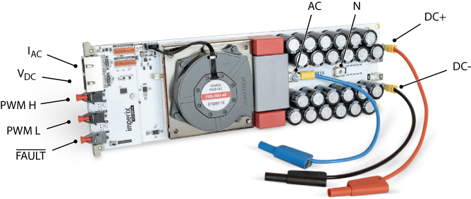
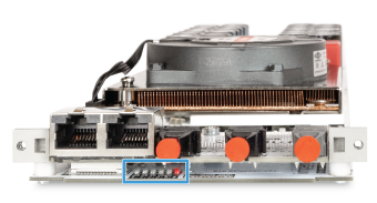
The assembly of power converters with the PEB-800-40 necessitates wiring on both the power and control sides. For this purpose, users are provided with the following elements:
- The switching node (AC).
- The DC bus positive (DC+), negative (DC-), and mid-point (N) terminals.
- Two analog outputs for the on-board sensors IAC and VDC (RJ-45 sockets).
- Two optical inputs for the high (H) and low (L) PWM gating signals.
- An optical fault output.
The integrated sensors do not utilize the Ethernet protocol for data transmission; rather, RJ-45 cables are capable of conveying analog signals due to their shielding and twisted-pair construction. A dedicated ±15V external supply is required for each onboard sensor, delivered through the RJ-45 cable. B-Box controllers provide this voltage. However, third-party controllers may necessitate an independent power source.
Gating signals are sent through standard 650 nm Plastic Optical Fibers (POF) or Plastic Clad Silica (PCS) fibers. No special coding is required: light ‘ON’ applies a positive voltage on the gate; light ‘OFF’ applies a negative one. Similarly, the optical fault output is in the light ‘OFF’ state to indicate a fault condition. This signal is retrievable by B-Box controllers utilizing an Optical Expansion Board.
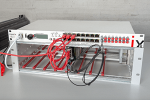
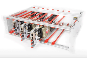
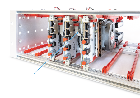
PEB-800-40 modules are compatible with two rack-mounting options: Type A open racks (3U) for easy module access, and Type C closed racks (4U) for enhanced safety and tool-free power stage wiring via banana connectors.


Protection and safety
The integrated on-board protection logic safeguards the PEB-800-40 module by continuously monitoring its operational state. Upon fault detection, the system immediately blocks the PWM gating signals. A key feature is that fault conditions are latched, maintaining a safe, inhibited state until a manual fault clearance is performed by the end-user. The monitored fault conditions are summarized below:
| Event | Flag | Fault triggering when |
|---|---|---|
| Over-voltage, or DC bus imbalance | VOLT | VDC > 850 V VDC,H or VDC,L > 450 V |
| Over-current | CURR | Long-term : |IAC| > |ISOA(FSW, VDC, DAVG)| (see Smart SOA protections) Short-term: |IAC| > 2 x |ISOA(FSW, VDC, DAVG)| (see Overload capability) |
| MOSFET desaturation 1-1 gating signals | DESAT | Excessive drain-source voltage during on-state or shoot-through, or GATE_H = 1 and GATE_L = 1 |
| Power supply error | P.SUP. | V5V < 4.5 V or V5V > 5.5 V V12V < 11 V or V12V > 13 V |
| Cooling error | COOL | TNTC > 80 °C Fan speed < 1000±200 rpm |
| Remote fault | RMT | Triggered remotely or locally |
Smart SOA protection
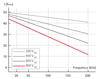
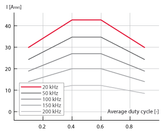
Excessive power dissipation in semiconductors poses a risk of permanent damage, necessitating strict adherence to the cooler’s power budget. Given that switching losses scale with both the switching frequency and the DC bus voltage, derating curves must be considered. Moreover, as an average duty cycle other than 0.5 results in asymmetrical losses between the upper and lower MOSFETs, another associated derating curve is also required. These curves are available in the datasheet and reproduced below for reference. They correspond to the maximum long-term (steady-state) current ratings.
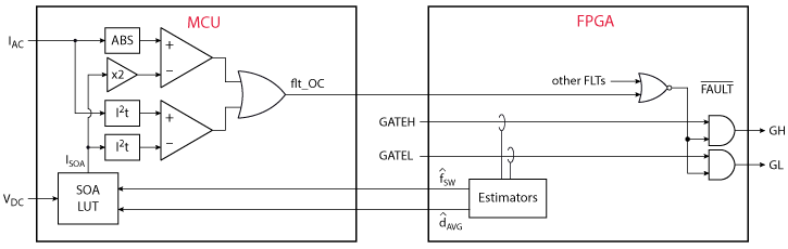
The PEB-800-40 continuously detects the operating point in real-time and dynamically adjusts the long-term over-current threshold accordingly. This guarantees that the module is always maintained within its Safe Operating Area (SOA).
Overload capability
Short-term overloads can be accommodated thanks to the modules’ thermal inertia. The PEB-800-40 permits overloads up to twice the rated current for 500 ms, using I2t-based protection. This protection has a variable tripping time, depending on the overload. For example, up to 120% of the long-term maximum current can be tolerated up to 4.6 seconds.
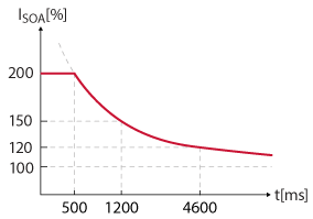
The following schematic illustrates the combined operation of both protections.
Fault signaling
Six red LEDs are present on the front side of the module, under the mezzanine, indicating the origin of the fault, when applicable. Additionally, errors are indicated on the LCD screen of Type C racks. The corresponding flags regroup the possible causes:
| Flag | ON | Blinking |
|---|---|---|
| VOLT | Over-voltage detected on the DC bus | DC bus imbalance |
| CURR | Over-current detected at the switching node (AC) | Excessive switching frequency |
| DESAT | Excessive drain-source voltage during on-state | 1-1 condition detected on the PWM signals |
| P.SUP. | Inadequate +12V power supply voltage | Inadequate +5V power supply voltage |
| COOL | Over-temperature on the cooler | Probable fan fault (no tachometer signal) |
| RMT | Remote fault flag active (triggered remotely or locally) | – |
The integrated logic generates a global fault indicator, which is made available via an optical output (see below). Fault clearance is performed by actuating the dedicated clear button, which is located either on the mezzanine of any module (for Type A open racks) or beneath the LCD screen (for Type C closed racks).


Modules can be interconnected in a daisy-chain configuration using flat cables to manage the system-wide fault state and control. This mechanism ensures the propagation of the global fault flag and the clear fault signal across all connected units.
- Global Fault Propagation: The detection of any local fault condition results in the assertion of the global fault flag, subsequently disabling all modules within the rack.
- Centralized Fault Clearance: Acknowledging a fault on any single module initiates a simultaneous reset of the fault state across all neighboring modules connected in the chain.
Furthermore, these flat cables facilitate the transmission of detailed power module status data (including active fault flags, fan speed, etc.) to the LCD screen of Type C racks.
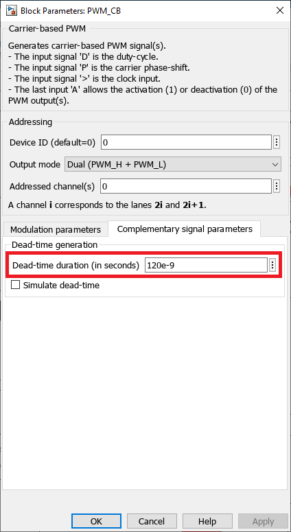
Minimum deadtime
The implementation of a dead time in the gating signals is necessary to prevent shoot-through. Given that the Pulse Width Modulation (PWM) signals originate from an external controller, the user bears the responsibility for applying the appropriate dead time. The Minimum dead time for the PEB-800-40 is 120 ns.
External protections with B-Box controllers
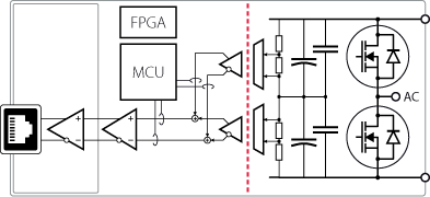
The PEB-800-40 includes integrated overvoltage and overcurrent protections calibrated to its maximum ratings. For applications where the overall system imposes more restrictive limits, B-Box controllers offer configurable hardware protections via an integrated analog front-end.
The figure below illustrates the principle for a B-Box 4: the PEB-800-40 sensor signals are converted to digital values and monitored by an FPGA-based comparator against user-defined high and low thresholds. Upon a threshold violation, the controller disables all PWM outputs within 1.6 μs.
More details can be found in Analog I/O configuration for imperix controllers (PN108).
Sensor configuration
With B-Box controllers
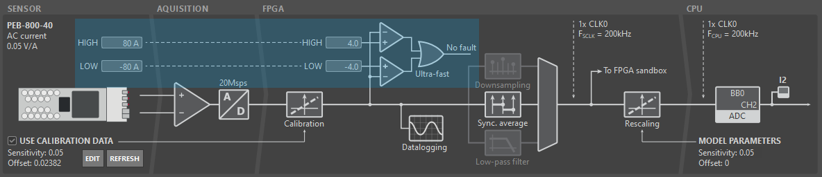
The complete chain from a PEB on-board sensor to the control algorithm running on B-Box 4 is shown below. It can be subdivided into two main parts, as explained in Analog I/O configuration on B-Box 4 (PN252):
- The hardware section includes the sensor, the analog-to-digital conversion inside the B-Box 4, and configurable hardware protections.
- The model section covers data downsampling to match the CPU rate, optional filtering options, as well as rescaling into a meaningful quantity (based on the sensitivity of the overall analog chain).
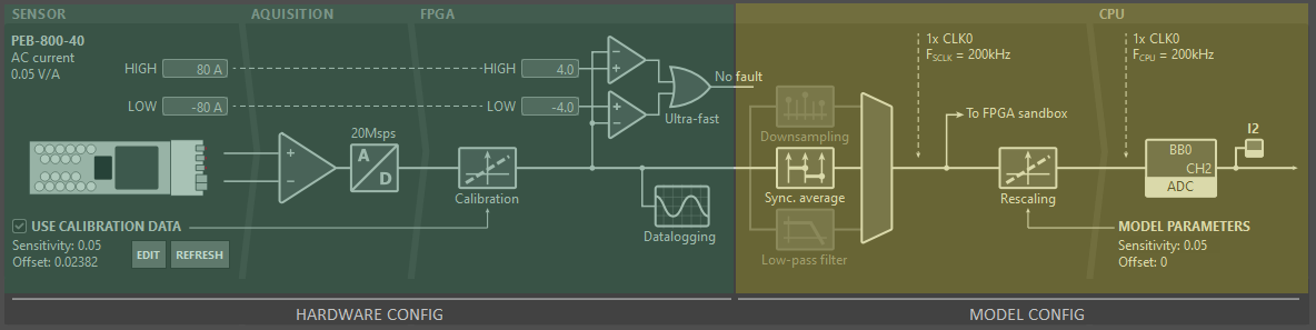
The hardware configuration is typically handled in Cockpit:
- Calibration data: The PEB-800-40 supports sensor auto-identification on the B-Box 4 (refer to PN255). Users can therefore leverage factory calibration data stored in the sensor’s EEPROM by selecting the Use Calibration Data checkbox.
- Protection thresholds: Users must define protection thresholds as previously specified. Thanks to auto-identification, the high and low limits are displayed in physical units (V or A) for simplified configuration.
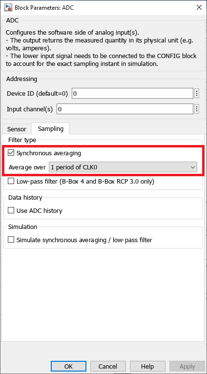
On the other hand, model parameters are indicated in the ADC block in Simulink/PLECS:
- Sensor: The integrated current or voltage sensor can be selected in the dedicated drop-down list to automatically load the correct sensitivity and offset. With B-Box 4, while the offset can be adjusted in the model, it is recommended to use the factory calibration data instead, as this parameter is intrinsically different for each device.
- Sampling: Synchronous averaging is the default recommended method, due to its excellent noise immunity and low delay. However, other Sampling techniques (PN258) are also available.

With other controllers
Any controller with ±5V analog inputs can retrieve the on-board measurements. To this end, the functional schematic of the DC voltage sensing circuit is shown below. The measurement of the DC voltage is implemented using precision resistive dividers on the two individual half-buses. Galvanic isolation is implemented using precision isolated amplifiers. The two corresponding measurements are subsequently combined by an operational amplifier, yielding a signal proportional to the total DC bus.
Similarly, the measurement of the output current (AC midpoint) is implemented using a high-precision shunt together with an isolated amplifier.
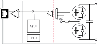
Measurements are accessible through RJ-45 connectors according to the pinout shown below. The external controller must supply ±15V (>10 mA) to power up the output amplifier of each analog chain. Also, the 1-wire line (pin 3) should either be left floating or connected to GND.

Application examples with the PEB-800-40
The PEB-800-40 modules are designed for versatile deployment, functioning either as standalone units for buck or boost conversion or as integrated components within more complex power topologies. The following articles provide comprehensive, step-by-step instructions for the assembly and commissioning of these systems:
- How to build a buck converter (PN119)
- How to build a three-phase inverter (PN170)
- How to build an interleaved boost converter (PN173)
Furthermore, Imperix offers an extensive library of technical articles detailing advanced converter architectures and sophisticated control methodologies. The following examples represent high-level applications that leverage the capabilities of the PEB-800-40: