Table of Contents
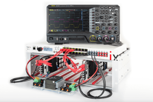
This document provides guidance for integrating imperix power modules into an open rack (type A). Intended for first-time users, the guide details essential mechanical considerations, auxiliary power supply requirements, and fault signaling configurations necessary for a successful installation.
Modules may also be housed in a closed rack (Type C or D), offering enhanced safety and facilitating tool-free manupulation thanks to banana connectors.
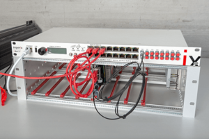
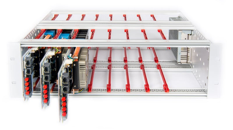
What is inside an open rack?
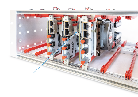
An open rack is a metallic frame that can hold up to eight imperix power modules. It consists of:
- Eight sets of plastic mounting rails to slide power modules into.
- An auxiliary power supply that delivers +12V/5V to the modules.
Each slot is fully independent, though all share a common auxiliary power supply. Consequently, users may populate any slot and combine different types of power modules as required. Compatible Imperix products are listed in the table below.
| Module | Topology | Status | Alternative rack |
|---|---|---|---|
| PEB-800-40 | SiC half-bridge | Active | Closed rack (type C) |
| PEB8024 | SiC half-bridge | NRND | Closed rack (type C) |
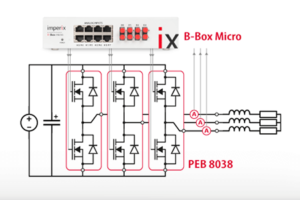
| PEB8038 | SiC half-bridge | NRND | Closed rack (type C) |
| PEB4050 | IGBT half-bridge | NRND | Closed rack (type C) |
| PEN8018 | NPC phase-leg | Active | Closed rack (type C) |
| PEH2015 | Full-bridge | Active | n/a |
| PEH4010 | Full-bridge | Active | n/a |
Auxiliary power supply
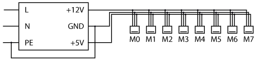
Each of the eight modules utilizes a dual-output power supply for its auxiliary circuitry. The +12V output is dedicated to the fan and gate drivers, while the +5V output powers all remaining components.
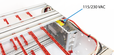
The open rack utilizes a Delta Electronics PMT-D1V100W1AA power supply. This unit features a manual 115/230 VAC selector switch that must be configured to match the local grid voltage prior to operation.
In early 2026, the power supply was upgraded to the Mean Well ADS-15512 to support the increased power demands of PEB-800-40 modules. Unlike the previous model, this unit features a universal input range compatible with 115/230 VAC and does not require a manual selector switch.
The specifications of both models are summarized in the following table:
| Specifications | PMT-D1V100W1AA | ADS-15512 |
|---|---|---|
| Output voltage (CH1) | +12 V | +12 V |
| Rated current (CH1) | 7 A | 11.5 A |
| Output voltage (CH2) | +5 V | +5 V |
| Rated current (CH2) | 3 A | 3 A |
| Rated power | 100 W | 153 W |
| Input voltage range | 100 ~ 120 VAC or 200 ~ 240 VAC | 100 ~ 240 VAC |
| Input frequency range | 47 ~ 63 Hz | 47 ~ 63 Hz |
Inserting power modules into an open rack
PEB modules
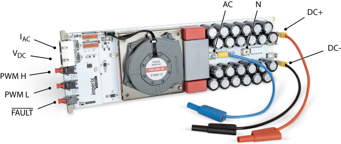
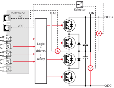
All PEB modules share the same connectivity, as presented in the PEB-800-40 quick start guide:
- The switching node (AC)
- The DC bus positive (DC+), negative (DC-), and mid-point (N) terminals
- Two analog outputs for the on-board sensors IAC and VDC (RJ-45 sockets)
- Two optical inputs for the high (H) and low (L) PWM gating signals
- An optical fault output
The integrated sensors do not utilize the Ethernet protocol for data transmission. Instead, RJ-45 cables are capable of conveying analog signals due to their shielding and twisted-pair construction. A dedicated ±15V external supply is required for each onboard sensor, delivered through the RJ-45 cable. B-Box controllers provide this voltage. However, third-party controllers may necessitate an independent power source.
Gating signals are sent through standard 650 nm Plastic Optical Fibers (POF) or Plastic Clad Silica (PCS) fibers. No special coding is required: light ‘ON’ applies a positive voltage on the gate; light ‘OFF’ applies a negative one. Similarly, the optical fault output is in the light ‘OFF’ state to indicate a fault condition.
Due to restricted access following installation, the AC and N terminals must be wired prior to mounting the module inside the rack. Connections should be secured using an M4 screw. Using an anti-loosening washer, and a suitable ring terminal (e.g., RND 465-00635) is recommended.
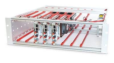
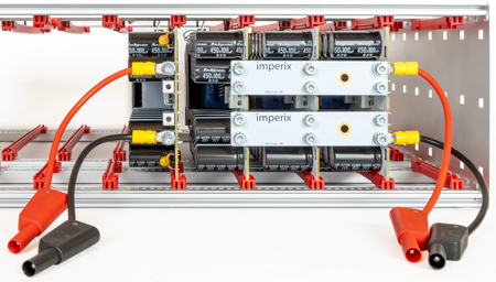
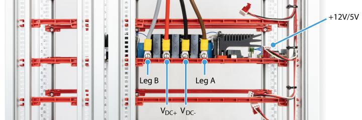
The next step is to slide the module into the rails and connect the auxiliary power supply, as shown below. The connector is keyed to ensure correct orientation and prevent the reversal of the +12V and +5V supplies.
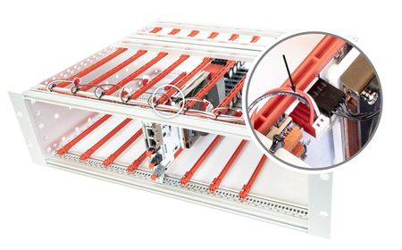
In case fault-related information must be shared accross the modules, flat ribbon cables (TE connectivity 2205065-2) can be used in a daisy-chain configuration. More information is given in the Fault signalling section below.
Finally, the DC bus terminals can be wired using either ring terminals or bus bars (sold separately).
PEN modules
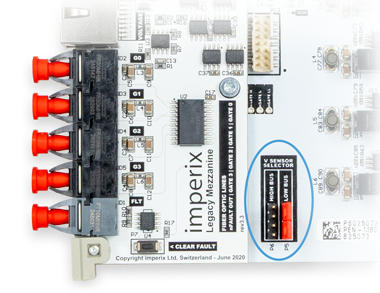
The installation of PEN modules follows the same procedure as for PEB modules, except for the onboard voltage sensor configuration. PEN modules use two sensors to monitor either the upper or lower DC half-bus, depending on the position of two jumpers. As these jumpers are difficult to access once installed, the desired measurement output must be configured before sliding the module into the rack.
PEH modules
In contrast to PEB and PEN modules, PEH power terminals are mounted on the top side. Also, fault sharing using the flat cables is not available. The installation is therefore simplified as follows:
- Slide PEH modules into the rack.
- Connect the auxiliary power supply (+12V/+5V).
- Wire the power stage using M4 fork terminals (e.g., Phoenix Contact 3240042).
Fault signaling
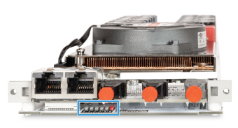
Six red LEDs located on the front side of the module (under the mezzanine board) indicate the origin of the fault, when applicable. The corresponding flags categorize the possible causes, as indicated in the table below.
Flag | Description |
|---|---|
| VOLT | Over-voltage detected on the DC bus, or DC bus imbalance |
| CURR | Over-current detected at the switching node (AC) |
| DESAT | Excessive drain-source voltage during on-state (PEB only), or 1-1 condition on the PWM signals |
| P.SUP. | Inadequate power supply voltage |
| COOL | Over-temperature on the cooler, or probable fan fault (no tachometer signal) |
| RMT | Remote fault flag active (triggered remotely or locally) |
When a fault occurs, the system remains in a fault state until manually cleared or the whole rack is power-cycled. The fault can be cleared by pressing the dedicated button located on the mezzanine. Clearance is only successful if the underlying fault condition is no longer present.
Fault sharing
The onboard logic generates a global fault flag, which can be fed back to the controller (if needed) via the optical output (see images above). This signal is inverted so that the absence of light signals a fault. When using B-Box controllers, this signal can be retrieved using an optical expansion board.
Faults can also be shared across PEB or PEN modules using daisy-chained flat cables (see assembly instructions above). This mechanism ensures that the global fault flag and clear signal propagate across all modules.
Coordinated tripping may be useful for faults that cannot be seen by the controller, such as cooling, desaturation, and power supply faults. However, for over-current or over-voltage faults, it is preferable not to rely on module-to-module fault sharing for the following reasons:
- The protections inside imperix controllers can be set to lower thresholds and offer faster response times.
- If an over-limit condition is detected by an imperix controller, the PWM signals are blocked even before the fault-sharing information is carried to all modules.
- Keeping the controller “blind” to power stage faults is generally not recommended, as the fault condition may require specific control actions.
Going further with the open rack…
A fully functional converter requires a controller, such as the B-Box 4, in addition to power modules. The following articles provide guidance to build a complete converter within an open rack.