Table of Contents
This document introduces the two variants of the closed rack (types C and D). Intended for first-time users, the guide details the auxiliary power supply requirements, the wiring process, and messages displayed on the LCD screen.
Modules may also be housed within an open rack (type A). This configuration offers greater flexibility, allowing different types of modules to be mixed and easily swapped.
What is inside a closed rack?
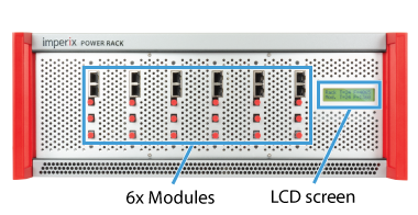
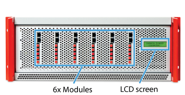
A closed rack is a complete metallic enclosure designed to house six or eight power modules. It consists of:
- Six or eight slots equipped with plastic mounting rails to hold power modules
- An LCD screen displaying status information
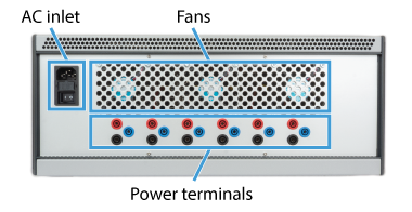
- Integrated enclosure-level variable-speed cooling fans
- An auxiliary power supply for the power modules, screen, and fans
Two types of closed racks exist, which differ by their front-side openings as well as the number of terminals on their rear side.
The compatible products with the Type C racks are listed in the table below.
| Module | Topology | Status | Alternative rack |
|---|---|---|---|
| PEB-800-40 | SiC half-bridge | Active | Open rack (type A) |
| PEB8024 | SiC half-bridge | NRND | Open rack (type A) |
| PEB8038 | SiC half-bridge | NRND | Open rack (type A) |
| PEB4050 | IGBT half-bridge | NRND | Open rack (type A) |
Type D racks are however exclusively designed to host PEN modules.
| Module | Topology | Status | Alternative rack |
|---|---|---|---|
| PEN8018 | NPC phase-leg | Active | Open rack (type A) |
Auxiliary power supply
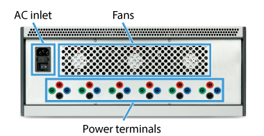
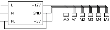
A dual-output power supply energizes the auxiliary circuits for all modules, as illustrated below. The +12V output is dedicated to the fan and gate drivers, while the +5V output powers all remaining components. For racks containing eight modules, two additional connectors are included.
Closed racks were originally equipped with a Delta Electronics PMT-D1V100W1AA power supply. In early 2026, this was upgraded to a Mean Well ADS-15512 to accommodate the higher power requirements of the PEB-800-40 modules. The specifications of both models are summarized in the following table:
| Specifications | PMT-D1V100W1AA | ADS-15512 |
|---|---|---|
| Output voltage (CH1) | +12 V | +12 V |
| Rated current (CH1) | 7 A | 11.5 A |
| Output voltage (CH2) | +5 V | +5 V |
| Rated current (CH2) | 3 A | 3 A |
| Rated power | 100 W | 153 W |
| Input voltage range | 100 ~ 120 VAC or 200 ~ 240 VAC | 100 ~ 240 VAC |
| Input frequency range | 47 ~ 63 Hz | 47 ~ 63 Hz |
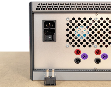
The AC inlet includes two 2A / 250V ceramic fuses (Bel 5HT 2-R) in a tray, as shown below. The left fuse is connected in series with the AC input to protect the auxiliary power supply, while the right fuse is a spare unit.
Wiring the power modules
Type C racks
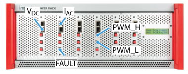
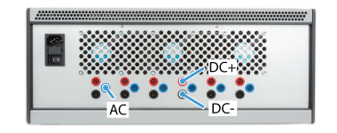
Wiring is required on both the power and control sides. For that, the following connections are provided:
- The switching node (AC)
- The positive (DC+) and negative (DC-) DC bus terminals
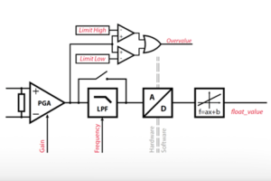
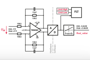
- Two analog outputs for the on-board sensors IAC and VDC (RJ-45 sockets)
- Two optical inputs for the high (H) and low (L) PWM gating signals
- An optical fault output
The integrated sensors do not utilize the Ethernet protocol for data transmission; rather, RJ-45 cables are capable of conveying analog signals due to their shielding and twisted-pair construction. A dedicated ±15V external supply is required for each onboard sensor, delivered through the RJ-45 cable. B-Box controllers provide this voltage. However, third-party controllers may necessitate an independent power source.
Gating signals are sent through standard 650 nm Plastic Optical Fibers (POF) or Plastic Clad Silica (PCS) fibers. No special coding is required: light ‘ON’ applies a positive voltage on the gate; light ‘OFF’ applies a negative one. Similarly, the optical fault output is in the light ‘OFF’ state to indicate a fault condition. This signal can be retrieved by B-Box controllers using an optical expansion board.
Type D racks
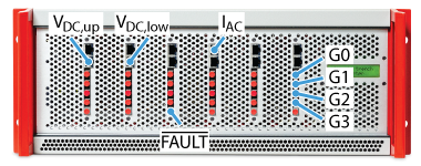
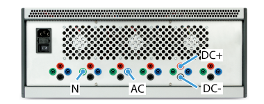
Type D racks provide a slightly different connectivity:
- The DC-bus midpoint terminal is also available (N).
- Four optical inputs for the PWM gating signals are available instead of two.
PEN modules use a single RJ45 connector to output the voltage of either the upper or lower DC half-bus, selectable via an internal jumper. Because this jumper cannot be accessed once installed in a closed rack, the modules are configured alternately from the leftmost slot to the rightmost slot, starting with the upper voltage. Further details on this jumper configuration can be found in the guide about open racks.
Status information and fault signaling
Modules are internally interconnected in a daisy-chain configuration via ribbon cables to enable global fault propagation and centralized fault clearance. This communication bus also transmits real-time status information to the LCD screen, informing the user about fan speeds, temperatures, and fault flags.
Booting and normal operation
When a closed rack is turned on, the LCD displays a booting message for 1 second:

After the boot, the screen displays the following information:
- The temperature inside the rack [°C]
- The highest fan speed of the three enclosure fans [rpm]
- The highest temperature among all the power modules [°C]
- The highest fan speed of all the power modules [rpm]

As long as there are no faults, the screen is refreshed every second.
Behavior under fault
Each module can generate any of the following local faults, immediately blocking the gating signals:
| Flag | Description |
|---|---|
| V. | Over-voltage detected on the DC bus, or DC bus imbalance |
| I. | Over-current detected at the switching node (AC) |
| D. | Excessive drain-source voltage during on-state (PEB only), or 1-1 condition on the PWM signals |
| P. | Inadequate power supply voltage |
| T.F | Over-temperature on the cooler, or probable fan fault (no tachometer signal) |
Detailed fault diagnostics are available on the LCD screen, and error messages will cycle continuously until the fault condition is resolved:
- A first message indicating the source of the fault. The possible sources are:
- “POWER MODULE FAULT” if the fault comes from one of the modules,
- “RACK COOLING ERROR” if there is an issue with the enclosure fans or internal temperature probes.


- Subsequently, the system displays a sequence of six or eight status messages (one per module) to identify local faults. If a fault is detected, the specific error type is reported. If the module is functioning correctly, the display provides real-time operating temperature and fan speed metrics.


- The last message displays the highest temperatures and fan speeds, as during normal operation:

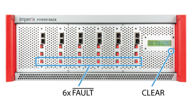
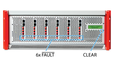
The modules’ logic generates a fault flag, which is made available via an optical output (see below) and propagated to the other modules. The fault can be cleared by pressing the dedicated button located below the screen. Clearance is only successful if the underlying fault condition is no longer present.
Going further with the closed rack…
A fully functional converter requires a controller, such as the B-Box 4, in addition to power modules. The following articles provide guidance to build a complete converter within a closed rack.