Table of Contents
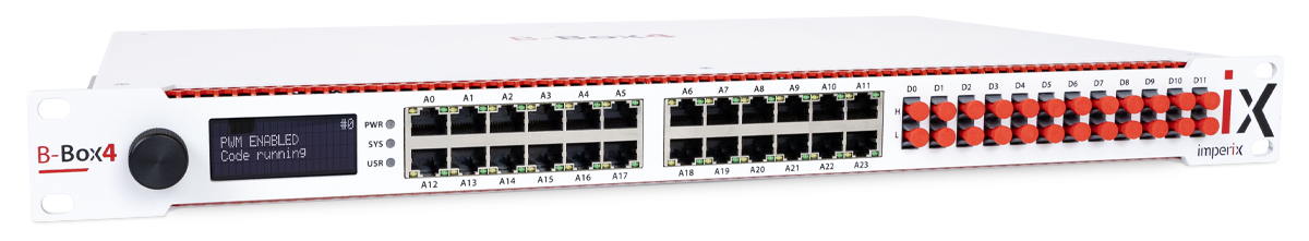
This B-Box 4 guide provides the necessary information to get started with imperix’s flagship controller.
To this end, readers are guided through the implementation of a “hello-world” application, which also serves as a software commissioning test. This simple application produces a sine wave on a DAC output, which is then read back through an ADC input.
Document outline
This document illustrates the workflow required to design, compile, and test a basic control example. The content is structured into two distinct parts:
- Conceptual overview: The first sections are presented as standard documentation, intended to introduce the necessary background, including:
- Software installation
- Converter simulation and control code generation
- Converter operation and monitoring
- Hands-on tutorial: This guide concludes with a practical, step-by-step walkthrough of running a “hello-world” application on the B-Box 4.
Installing the software
To program its controllers, imperix provides two Software Development Kits (SDKs):
- The ACG SDK for Automated Code Generation (ACG) from Simulink or PLECS.
- The CPP SDK for development using C/C++ code.
The following sections are dedicated to the ACG SDK, which contains plug-in blocksets for MATLAB Simulink and PLECS. It therefore requires a recent version of either software, along with the code generation tools. Detailed instructions for installing the SDK can be found in the Installation guide for imperix ACG SDK. Essentially, the main steps can be summarized as:
- Installing (if not done already) the third-party tools, namely Simulink or PLECS, along with the required code generation add-ons.
- Downloading and running the installer for the ACG SDK. Download links for either SDKs are available on https://imperix.com/downloads/.
- For Simulink, a MEX compiler for C++ must be installed. The imperix installer takes care of the rest of the configuration.
- For PLECS, the path of the freshly installed Imperix_Controllers target support package (
C:\imperix\BB3_ACG_SDK\plecsby default) must be added to the PLECS Target support packages path in the PLECS preferences.
For users of the CPP SDK, guidance regarding installation and first steps can be found in PN146.
Developing control for the B-Box 4
Once the software is installed, programming the B-Box 4 begins with preparing a control model. These steps are summarized in the following tutorial video, in which Simulink is featured. Most of the content also applies to PLECS.
Users often choose to start from a pre-existing example from the knowledge base. It is also possible to start from scratch using the imperix template model, available in the ACG SDK’s installation folder.
More details on the first steps with the ACG SDK (for both Simulink and PLECS) are given in PN134.
Imperix control files are structured into two distinct subsystems: the Controller (encompassing the control algorithm and the simulation models for the B-Box’s own resources) and the Plant (modeling the power stage).

The Controller subsystem
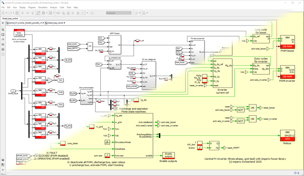
The Controller subsystem essentially contains the control algorithms, which can be developed using blocks from the imperix Control library as well as any standard Simulink/PLECS block supported by code generation. This subsystem has two purposes:
- During offline simulation, the control algorithms are precisely emulated, thanks to accurate models of the B-Box 4’s physical peripherals (internal resources and I/Os) contained within each imperix block. By running simulations before code is generated, users can precisely anticipate the control’s performance and pre-tune the implemented algorithms.
- After code generation, C/C++ code equivalent to the Controller subsystem is automatically generated, leveraging the B-Box 4’s own hardware configuration routines. More information on the hardware is found in the B-Box 4’s datasheet.
In Simulink, switching between these two model execution purposes can be done inside the CONFIG block. No equivalent mechanism is implemented in PLECS, as these distinct purposes are natively handled by PLECS.
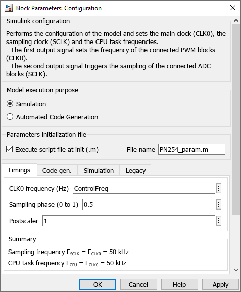
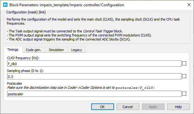
The CONFIG block is particularly important as it also sets the configuration for the main control task, including the interrupt rate and sampling configuration. Further details on the purpose of the clock signals and how to properly use them are given in PN135 for Simulink and PN136 for PLECS.
On top of that, two configuration settings require special attention. While these parameters can be modified at any time, applying changes will require recompilation. It is therefore recommended to address them beforehand.
- Configuration of the analog inputs: The model-dependent part of the configuration of the analog input chain(s) must be correctly set to guarantee the proper scaling of the measured data. The related details are given in configuring the B-Box 4 I/Os.
- Selection of the PWM deadtime: The deadtime between complementary PWM signals must be adequate for the connected power hardware. Recommended values for imperix power modules can be found in their respective datasheets. More information on how to select the proper deadtime is provided in PN115.
The Plant subsystem
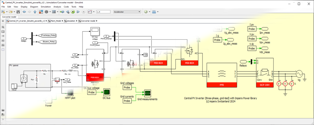
The Plant subsystem contains the simulation model of the physical system being controlled (e.g., power converters, micro-grid, electrical machines, etc.).
To accurately simulate the plant alongside the control algorithms, imperix provides a Power library modeling the company’s power products, including half-bridge power modules, sensors, connection panels, and more. Documentation on the Power library is provided in PN150.
It is essential to note that the Plant subsystem is ignored during the code generation process, as real equipment is used during experimental activities (no code is required for this subsystem).
Programming the B-Box 4
Generating run-time code
As previously detailed, the same model is used for both simulation and code generation. To build the code, press Ctrl+B in Simulink (ensure the CONFIG block is set to “Automated Code Generation”) or Ctrl+Alt+B in PLECS. The software will automatically generate code for the Controller subsystem, compile it, generate a bitfile, and transmit the latter to Cockpit for upload.
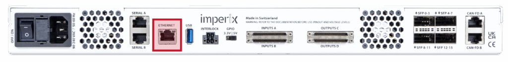
Connecting the B-Box 4 to the PC
The B-Box 4 must be connected to the PC via Ethernet. The B-Box 4 can either be connected to an existing local network or directly to the Ethernet port of a computer (as a point-to-point connection). It will then automatically be assigned a dynamic IP. If needed, details on these steps and the possible network configurations are given in Programming and operating imperix controllers.
– Licenses are usually pre-loaded on the controllers.
– Only master controllers, i.e. controllers that run the control code, need licenses, but slaves do not.
– The software can be installed on an unlimited number of computers.
More details on the licensing of imperix software are given in imperix licensing.
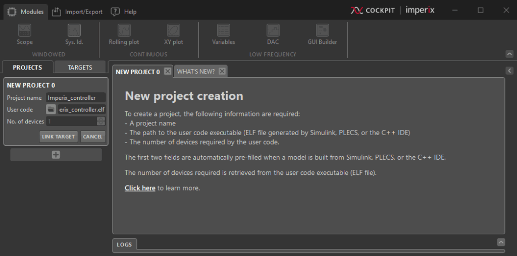
Loading the code with Cockpit
Once the code is built from Simulink or PLECS, Cockpit opens automatically and invites to create a new project. Projects associate a model (Simulink or PLECS) with a target (the controller receiving the corresponding runtime code). More details regarding the Projects and the Targets views are given in the Cockpit User Guide.
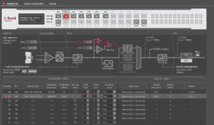
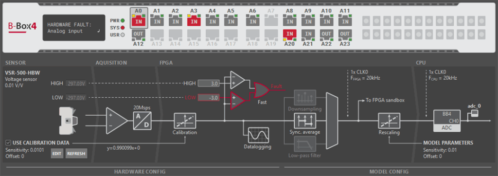
Configuring the B-Box 4 I/Os
An essential step before powering the system is to configure the hardware section of the analog inputs. Indeed, the B-Box 4 possesses two very distinct sections:
- The hardware configuration section, which corresponds to parameters stored inside the B-Box itself. This section notably includes the sensor calibration data and the hardware protection thresholds. These are resident inside the hardware and are entirely independent of the model. They can be configured either directly in Cockpit under the TARGETS tab in the Analog I/Os section, or using the device front panel (LCD screen and rotary button)
- The model configuration section, which corresponds to parameters stored inside the Simulink/PLECS model. This section notably includes filter configuration and ADC measurements rescaling. These parameters are configured inside the ADC blocks and can only be modified inside Simulink or PLECS. As mentioned earlier, changes to these parameters require recompiling the code.
A comprehensive description of the complete input chain is provided in Analog I/O configuration on B-Box 4. An equivalent view is provided in Cockpit by accessing the Target configuration.
The hardware configuration includes the following parameters:
- Sensor type and parameters: With the latest Imperix sensors and modules (sold in 2026 and after), the B-Box 4 automatically recognizes which sensor is connected and reads factory calibration settings (if available). More information is given in Sensor auto-identification on B-Box 4.
- Safety limits and reaction speed: It is highly recommended to always and systematically configure these limits for every measurement channel. Accurate configuration is vital for hardware integrity and safe prototyping. Specific information for the configuration of the protection thresholds is given in Analog I/O configuration on B-Box 4. Generic information and guidance regarding the use of protections is provided in Over-current and over-voltage protection.
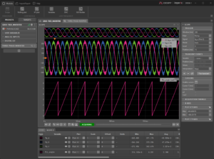
Monitoring the execution using Cockpit
The Cockpit user guide explains how to operate the converter from Cockpit. In summary, users can drag variables from the sidebar list into visualization modules, such as the Scope or Rolling Plot, allowing them to monitor signals and operate the converter in real time.
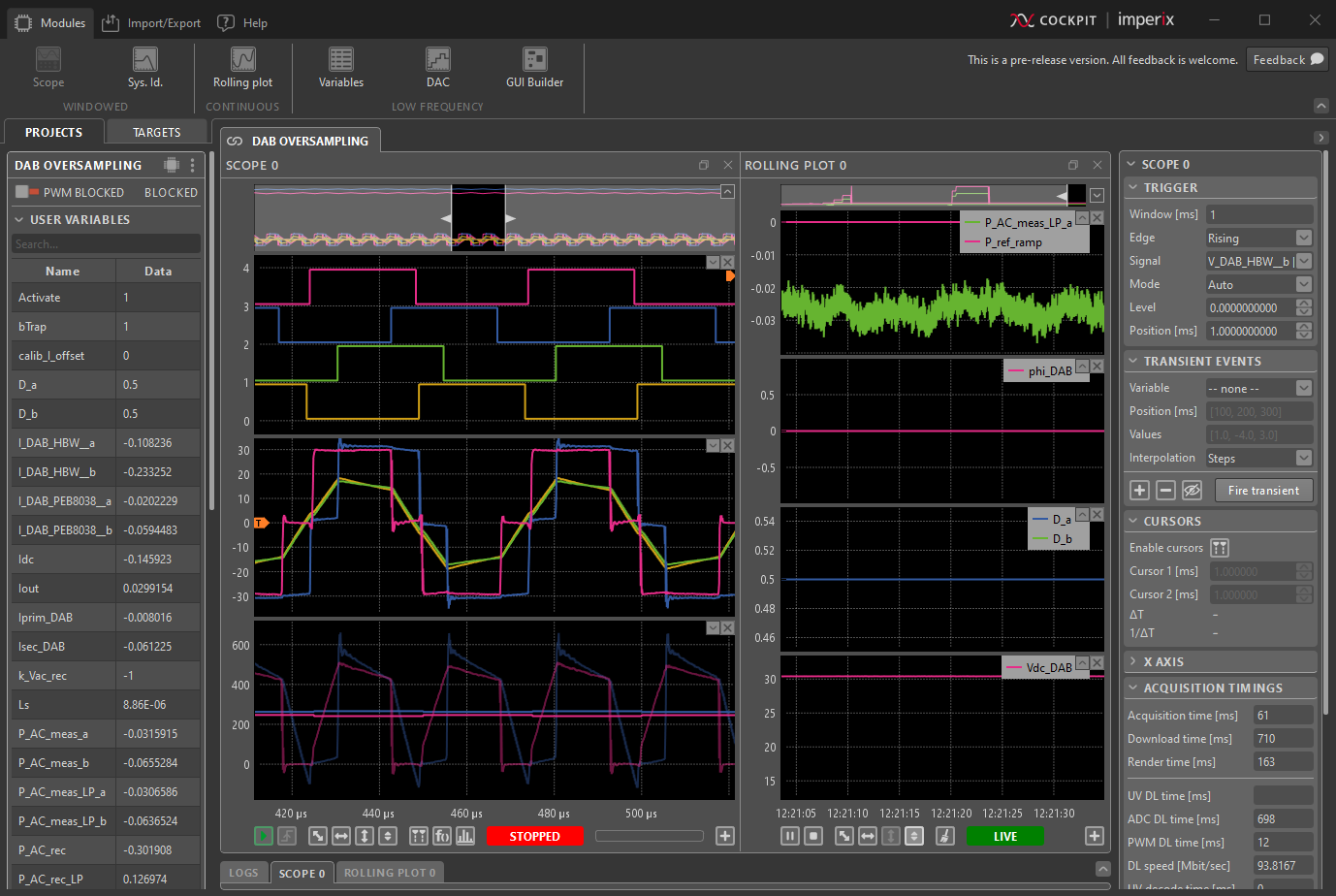
A primary feature of the B-Box 4 is its fast sampling capability of up to 20 Msps, with the option to display all oversampled data within Cockpit. Any probe or variable connected to the output of an ADC block, in the Simulink/PLECS model, will display the oversampled data. It is worth noting that the oversampled variables can be utilized in most Cockpit modules, including the spectral analyzer. Additional details on the supported sampling techniques are given in sampling techniques for power electronics.
Similarly, generated PWM signals, sampled at 250 MHz, can also be displayed inside of Cockpit. All instantiated PWM signals are automatically made available in the Cockpit user variables list.
Hello world application
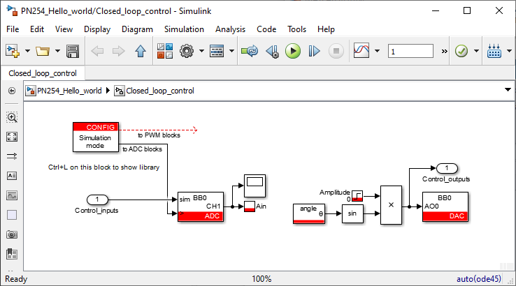
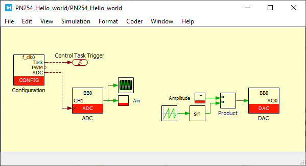
The final section of this B-Box 4 guide provides step-by-step assistance to run a “hello-world” example. The goal is to produce a sine wave on a DAC output that is subsequently read back through an ADC input. The corresponding Simulink and PLECS models are given below.
This procedure can also serve as a software commissioning test. It indeed validates that the software installation, license, code generation toolchain, and communication with the target are functioning correctly. No power equipment is required for this test; only a B-Box 4 controller and an RJ45 cable are needed.
Software Setup
This section assumes that the ACG SDK is already installed on the PC. For details on how to install the ACG SDK, please refer to the Installation guide for imperix ACG SDK.
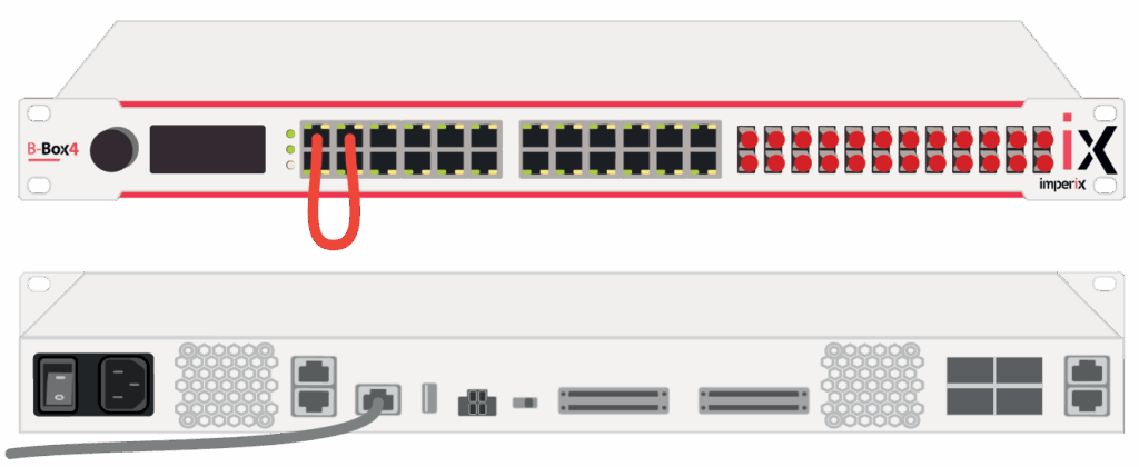
Hardware Setup
- Power on the B-Box 4.
- Connect it to the PC using the Ethernet port.
- Connect an RJ45 cable between analog channels A0 and A1.
In Simulink or PLECS
- Download and open the provided control model (choose between Simulink or PLECS according to the environment of choice). It includes the following blocks:
- CONFIG: sets the control interrupt frequency and sampling phase
- ADC: configured on analog channel 1, reads the generated DAC signal
- Probe: used to display the signal read by the ADC directly on Cockpit
- Tunable parameter: used to change the amplitude of the generated sinwave in real-time from Cockpit
- Standard blocks to generate a sine wave
- DAC: configured on analog channel 0, produces the sine wave
- Run the simulation by pressing Ctrl + T and observe the generated sine wave in the scope block.
- After validation in simulation, build the code by pressing Ctrl + B in Simulink (the CONFIG block should be set to Automated Code Generation) or Ctrl + Alt + B in PLECS. Cockpit should open automatically at the end of the process.
In Cockpit
- In Cockpit, link the project to the target by clicking on the LINK TARGET button on the top left panel in the Project tab.
- Cockpit should automatically detect the B-Box 4 and display it in the list of available targets under the Target tab. Select the B-Box 4 and click on LINK PROJECT.
(If the B-Box 4 does not appear automatically in the list, its IP can be entered manually by clicking on Can’t find your target? at the bottom of the target list. The B-Box 4’s IP can be accessed from its front panel by navigating the menu to the Ethernet section.) - Linking the project to a target automatically opens a project view. Add a scope module to the project by clicking on the scope icon at the top left.
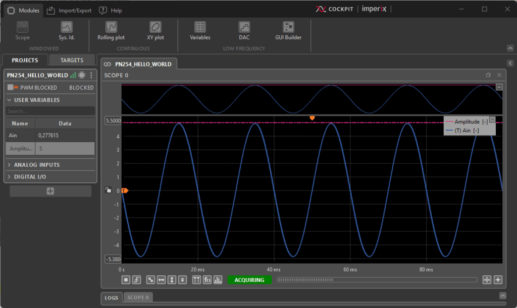
- Drag and drop the variable Ain into the scope from the list of variables on the left side of Cockpit.
- Change the amplitude of the sine wave by editing the variable Amplitude in the list of variables. A sine wave of the corresponding amplitude should be displayed in the scope.
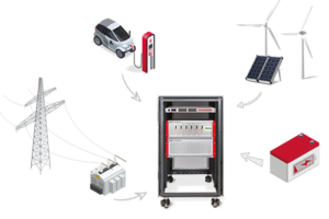
To go further
As a next step, the current-controlled buck converter tutorial is recommended as an introductory example for implementing control with Imperix power products. For the commissioning of pre-configured cabinets, a comprehensive hardware overview is given in the Power electronic bundle – quick start guide. Finally, the full capabilities of the B-Box 4 could be leveraged in an application such as a Solid-state transformer (SST) for MV-LV smart grids.