
Table of Contents
Imperix products are designed to prioritize safety, giving users the confidence needed to move straight to laboratory testing as soon as possible.
In this context, this article provides insights into how their over-current and over-voltage protections work to ensure the safety of personnel and equipment during operation, and points to relevant resources to ensure the correct configuration of these features.
Protection of imperix equipment
Imperix equipment can be easily integrated in compliance with safety requirements. With respect to equipment protection, imperix systems rely on two categories of devices and mechanisms:
External energy-limiting devices
Energy-limiting devices (circuit breakers, fuses, TVS, etc.) are used when required, typically with equipment intended for connection to the utility grid. By their nature, energy-limiting devices can break a fault (current or voltage) but cannot detect a fault early (i.e., before a critical energy level). This provides an indispensable layer of protection, but which is also too slow to prevent damage (a few to hundreds of milliseconds), notably to power semiconductors.
In a power electronics environment, such safety devices can be considered effective only against fire risks. For the vast majority of other purposes, they offer insufficient limitation of the fault energy, which can already significantly damage the equipment. Notably, supplementary mechanisms offering lower thresholds and/or faster reaction times are indispensable for protecting power semiconductors.
Fast threshold-based protections
Fast threshold-based protections guarantee reaction times consistent with typical current and voltage rise rates in power electronic systems (down to sub-microseconds). These operate by blocking the semiconductor devices before a critical level is reached, leaving the currents to vanish naturally. This is very effective with voltage source converters (VSCs). However, such protections cannot cover all types of faults, notably those caused by the free-wheeling current paths that inevitably exist in most power switches.
Imperix equipment offers three distinct types of fast threshold-based protections:
- Fixed hardware protections inside imperix power modules. These implement non-configurable over-current, over-voltage, and over-temperature thresholds, set at the modules’ maximum admissible ratings (e.g., PEB-800-40). These represent last-resort protections, which can prove useful when imperix modules are used with third-party controllers. However, the pre-programmed thresholds may prove excessive for the overall application or other equipment.
- Programmable hardware protections inside imperix controllers. These implement easily configurable thresholds that can be adjusted to match the planned operating points closely. Different protection characteristics exist among imperix controllers (see below).
- User-defined software protections inside the application software. These do not exist by default, but can always be implemented inside the control algorithms, typically using software comparisons. Despite a slower reaction time (which is a function of the control execution rate), software protections can easily implement non-constant thresholds or be activated/deactivated as a function of the system’s operating state (e.g., a minimum-voltage protection on a DC bus is extremely inconvenient otherwise).
An example involving all three layers of protection is given further down the article.
Principles of use and operation
On all imperix controllers, hardware protections are implemented as described in PN263. In particular, the programmable safety limits operate as follows:
- When an overcurrent or overvoltage occurs, the imperix controller instantly blocks all PWM outputs and switches its operating state to FAULT.
- A log message is available in Cockpit indicating which channel the fault occurred on. On B-Box 3 and 4 devices, the fault source is also indicated by a steady orange LED on the corresponding RJ45 socket.
- Once the root cause of the fault is well understood by the operator, the fault can be acknowledged, reverting the system to its BLOCKED state.
- PWM outputs can then be re-enabled in Cockpit.
The different core states that can be taken by imperix controllers are further documented in PN261.
The protections available on imperix controllers are compared in the table below. Other differences between them are described in PN250. Product notes related to a specific imperix controller are linked below:
- Programming the protections on the B-Box 4
- Programming the protections on the B-Box 3 (RCP)
- Programming the protections on the B-Box 3 micro
- Protections on the TPI 8032
- Protections on the B-Board 3 (PRO)
| Controller | Implementation | Configurable | Range | Speed | Configuration |
|---|---|---|---|---|---|
| B-Box 4 | Protected firmware | YES | ±10V | Ultra: <800ns Fast: 1.6µs | in Cockpit or using the front panel |
| B-Box 3 | Hardware comparators | YES | ±10V | Fast: 1.6µs | with Front panel 2 |
| B-Box micro | Protected FPGA firmware | YES | ±5V | Fast: 1.5µs | in Cockpit |
| B-Board PRO | N/A | N/A | N/A | N/A | N/A |
| TPI 8032 | Protected firmware 1 | NO | True values | Fast: 4µs | Not configurable |
1 The external analog inputs of the TPI 8032 do NOT offer hardware protections.
2 Saving/restoring the protection configuration requires a USB key on the B-Box RCP3.0, as it is entirely independent of Cockpit.
Quick configuration guidelines
– The to-be-protected quantity is measured with a working sensor that is effectively wired. As obvious as this seems, it is key to double-check that all relevant connections are actually made to the controller.
– The configured thresholds are correctly computed and applied. When in doubt, tests should be conducted with reduced test thresholds.
Selection of the protection thresholds
When working with imperix equipment, user-defined over-current and over-voltage thresholds shall be selected to protect the imperix equipment, but also the surrounding equipment.
Indeed, safety limits defined on the imperix controller also help protect auxiliary equipment. An elementary but critical example is the overvoltage protection of a DC bus, which is fundamental to protecting a DC power supply connected to that bus, especially if that source is unidirectional and/or rated at a lower voltage than the imperix modules. As such, imperix recommends to:
- Always select protection thresholds as close as possible to the planned operating points.
- Be very careful when including a margin in selecting the thresholds. The overload capability of power electronic circuits is generally extremely limited.
- Seek to constantly consider the weakest element in the system, as it may not necessarily be a power module, but a power supply, a cable, a resistor, etc.
- Test protections with lower limits in case of any doubts.
Scaling of the protection thresholds
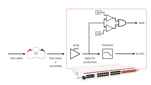
The quantities measured by imperix controllers go through the analog chain, as shown in the figure below. The protection acts on either the pre-conversion ADC value (B-Box 3) or the post-conversion ADC values (B-Box 4, B-Box micro, TPI). In both cases, the ADC value can be computed using the following equation:
$$ \text{value for protection} = \text{true value} * \text{sensor sensitivity} * \text{programmable gain}$$
| Controller | Programmable gain | Range for protection thresholds |
|---|---|---|
| B-Box 4 | 1x | ±10V |
| B-Box 3 | Configurable on front panel (1x, 2x, 4x, 8x) | ±10V |
| B-Box 3 micro | 1x | ±5V |
Configuration of the protection thresholds
B-Box 4
Detailed information regarding the configuration of analog I/Os is given in PN252. Specifically for the configuration of the safety limits, two cases should be distinguished:
- The B-Box 4 can automatically identify and read the sensitivity and offset information from compatible sensors (see PN255 for more details). In this case, safety limits can be configured in true value, i.e., typically as a voltage or current before the sensor (e.g., in hundreds of Volts, or Amperes).
- With older or third-party sensors, auto-identification is not available. In this case, safety limits must be configured based on the protection value, i.e., by manually considering the sensor sensitivity.
To configure the safety limits, both Cockpit and the front panel (LCD screen and button) can be used. Two safety-related settings are relevant:
- The safety limits (HIGH and LOW thresholds): between -10V and +10V.
- The reaction speed: ULTRA-FAST (800ns) or FAST (1.6us). FAST is recommended, except for extremely fast switching applications with high dI/dt.
B-Box 3 (RCP)
Detailed information on the analog input stage is given in PN105. This note also provides complete details regarding the configuration of the safety limits. In short:
- Limits can only be configured using the front panel (LCD screen and rotary button).
- Thresholds can either be enabled or disabled. An ON/OFF setting is available for that.
- On B-Box 3, all safety limits must be configured as a voltage on the ADC, taking into account the programmable gain (G=1, 2, 4, or 8) if different than unity :
$$ \text{threshold} = \text{true limit}*\text{sensitivity}*\text{programmable gain}$$
B-Box 3 micro
Configuration of the safety limits on B-Box micro must be done using Cockpit in the dedicated “Analog inputs” tab of the target information (“Targets” pane). More information is given in PN106.
With B-Box micro, safety limits must be configured as a voltage on the ADC, within -5V and +5V. Both thresholds can be either turned on or off simultaneously.
TPI 8032
The TPI 8032 has a built-in protection circuit against overcurrent, overvoltage, and overtemperature. The protection thresholds are dynamically configured based on the switching frequency and DC bus voltage, accounting for the necessary derating. The corresponding protection thresholds are not user-configurable.
External analog inputs cannot implement protections. Custom over-current or over-voltage detection mechanisms with more complex logic can nonetheless be implemented at the application-level software (e.g., Simulink/PLECS model).
B-Board 3 (PRO)
The B-Board PRO does not offer safety limits on its analog inputs. However, fault-line inputs allow the integration of external fault flags/triggers into the fault manager, thereby blocking PWM outputs accordingly. Additional details can be found in the datasheet.
Example: protections in practice
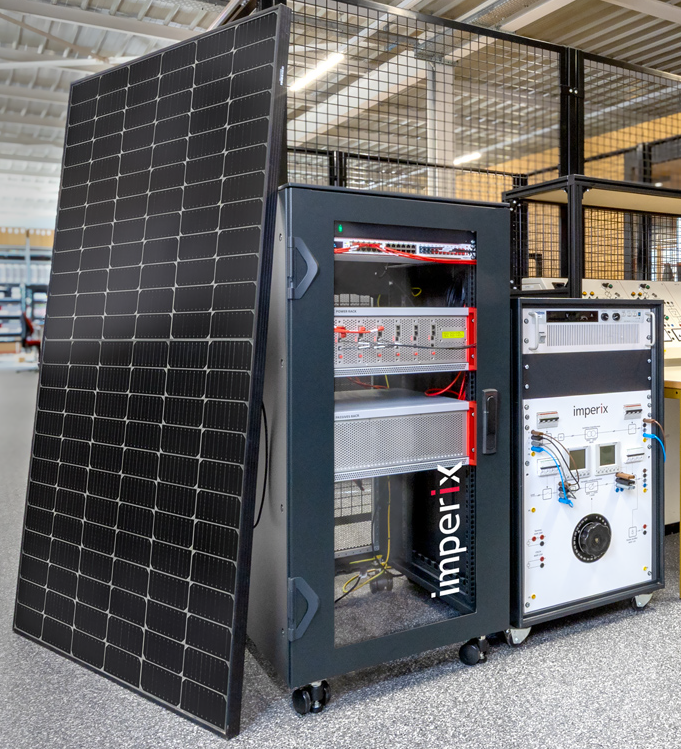
The application note AN003 provides an example of how the various protection mechanisms come together to provide comprehensive protection.
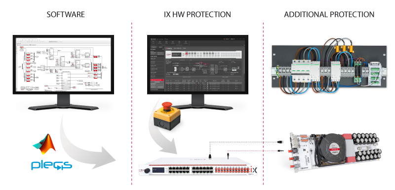
Simulink-based FSM
A finite-state machine ensures the precharge relays are in the correct position. Log messages detail why a fault has occurred. Ultra-fast response times are not required.
Safety limits on B-Box 4
For high-speed safety mechanisms such as over-current and over-voltage protection, the configurable thresholds on the B-Box 4 are ideal, reacting within 1.6us.
Module-based protections
In the event of a threshold misconfiguration, the module-based protections (e.g., PEB-800-40) serve as a last resort, protecting the modules from damage caused by inappropriate operation.
Additional protections and breakers
A circuit breaker ensures that the system is de-energized from the grid in case of a critical malfunction. The 16A device triggers somewhere between 80A and 160A, breaking up to 10kA.
In this example, several measurements are key to the system protection:
PV-side current
This protection benefits the PV panel, the inductor, and the boost power module. The corresponding threshold is set to the lowest of all three constraints.
PV-side voltage
This protection prevents the application of a potentially damaging voltage to the PV panel.
DC bus voltage
This protection benefits the power modules and the DC power supply during intermediary tests. It is set to the lower of the two constraints.
Grid currents
These protections mostly benefit the power modules. They are sufficient for their protection provided that the DC bus presents sufficient voltage.
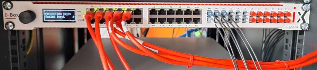
With the B-Box 4, fault source identification is displayed on the screen, the RJ45 LEDs, and Cockpit. If the RJ45 cables are labeled with the signal they carry, this is a quick way to trace the fault back to its source.
In this picture, some over-current faults have been triggered, instantly placing the controller in the FAULT state.

 By Jessy Ançay • November 21, 2025 • PN254
 By Daniel Blardone • February 15, 2024 • PN107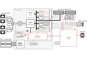
 By Shu Wang • July 7, 2026 • PN263