
Table of Contents
Imperix controllers possess protection mechanisms that operate fully independently from the user app CPU, the supervisor CPU, and the FPGA. This guarantees that the protections can always be trusted, even if the software or the custom FPGA logic isn’t completely reliable (yet).
A typical example of the use of hardware protections is a protection trip caused by an over-value (e.g., over-current) on an analog input channel. Another example is the failure to respect the control processing timings (loss of real-time).
In the event of such faults, all PWM outputs are immediately blocked, thereby preventing damage to the power stage. Successively, the controller is switched to the FAULT state, preventing outputs from being re-enabled before the root cause is clearly identified.
This page provides details on the implementation of hardware protections on imperix controllers, as well as their management at the software level. More general information on the operating principles of imperix controllers is given in PN261.
(PN257) Over-current and over-voltage protection
(TN181) Safety recommendations for working in the lab
Protection system architecture
At the hardware level, all fault signals are routed to a central fault manager inside the FPGA, which oversees the system’s operating state and controls the global activation of PWM outputs. The fault manager is also coupled with external logic, implemented on a dedicated FPGA in the B-Box 4 and on discrete electronics on other devices. Below is an overview of how protections are implemented on the B-Box 4.
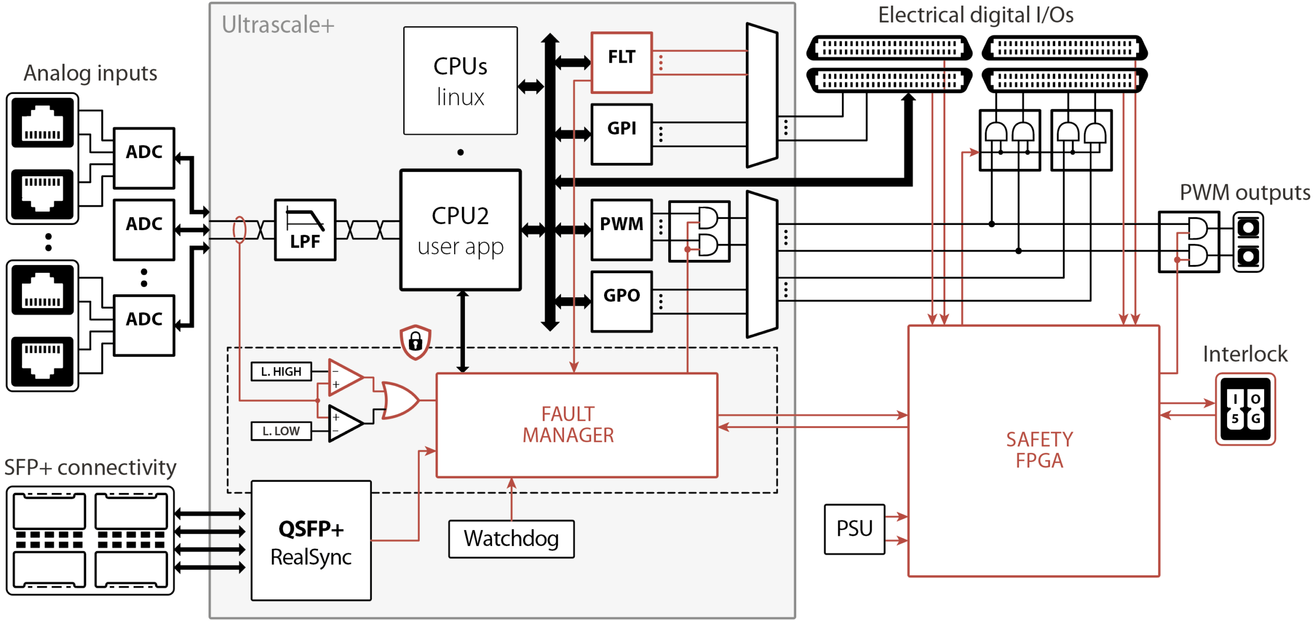
At the software level, the protection system authorizes or prevents the generation of PWM gating signals based on the controller’s so-called core state. Three distinct states are possible in relation to the operating state of the power stage:
- BLOCKED: The controller is operating normally, but all PWM outputs are inhibited. The CPU control task is hence running (including all the contained control algorithms and communication functions), but the power stage remains blocked.
- OPERATING: The controller is operating normally and all PWM outputs are normally produced. The power stage is actively driven.
- FAULT: An error occurred, and the system is awaiting acknowledgment. All PWM outputs are blocked similarly to the BLOCKED state.
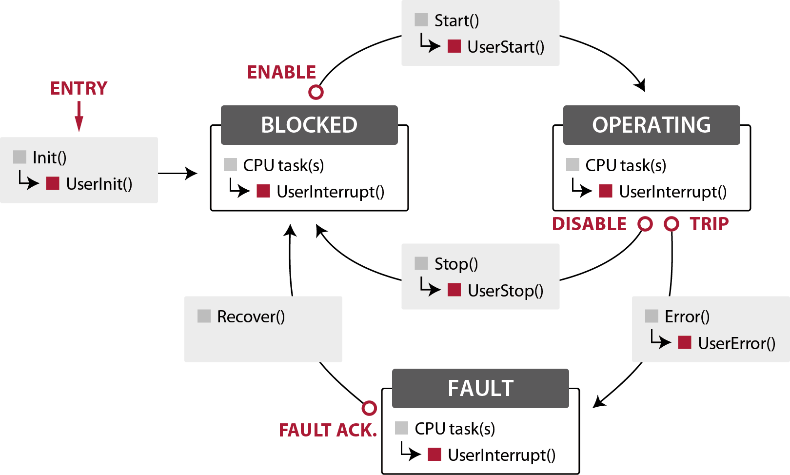
More information on the core state machine and its related transitions is provided in PN261.
Protection tripping
Operating principles
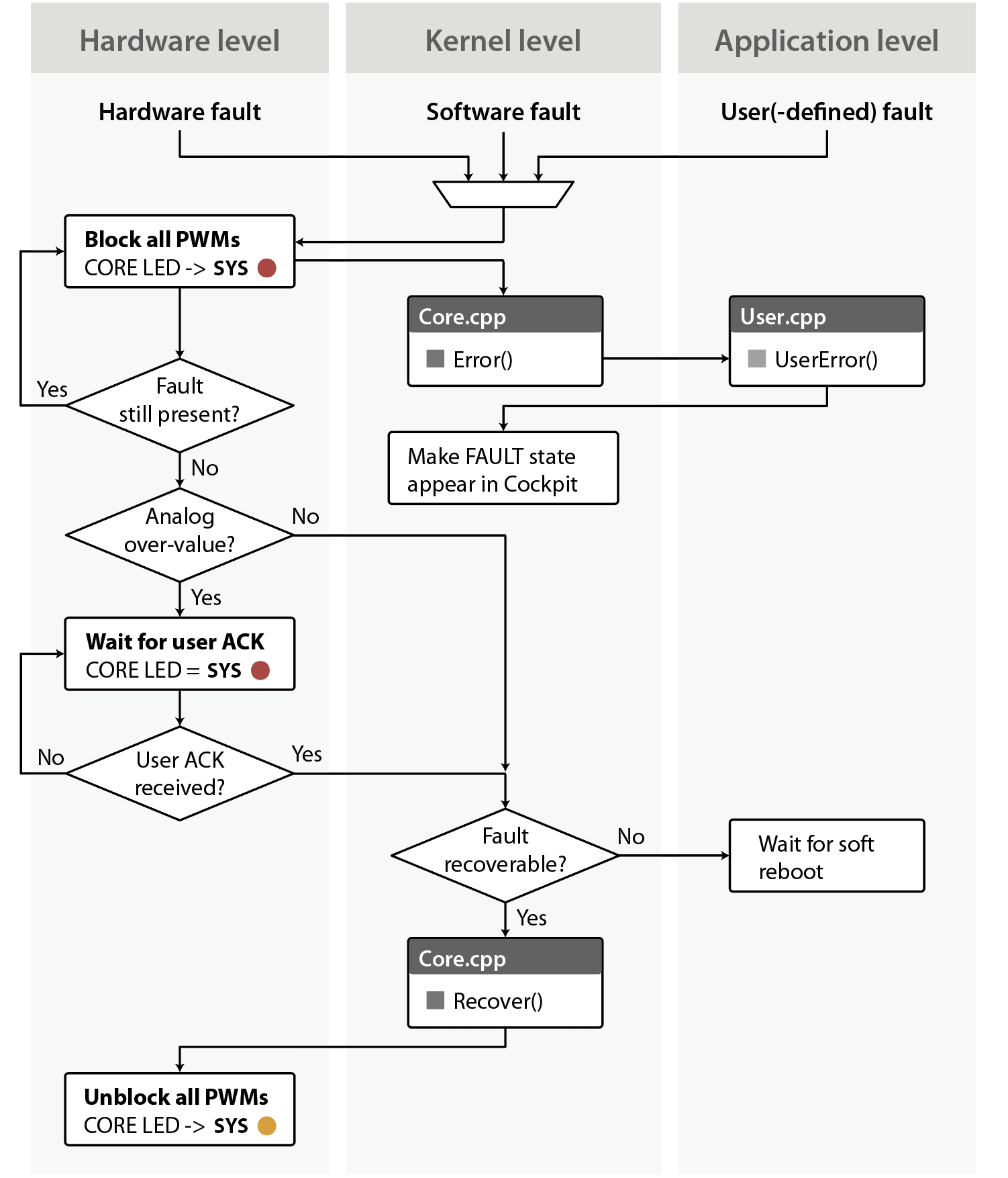
The illustration below shows the protection trip and acknowledgment sequence using the analog over-value protection as an example. In case of a fault, the following sequence takes place:
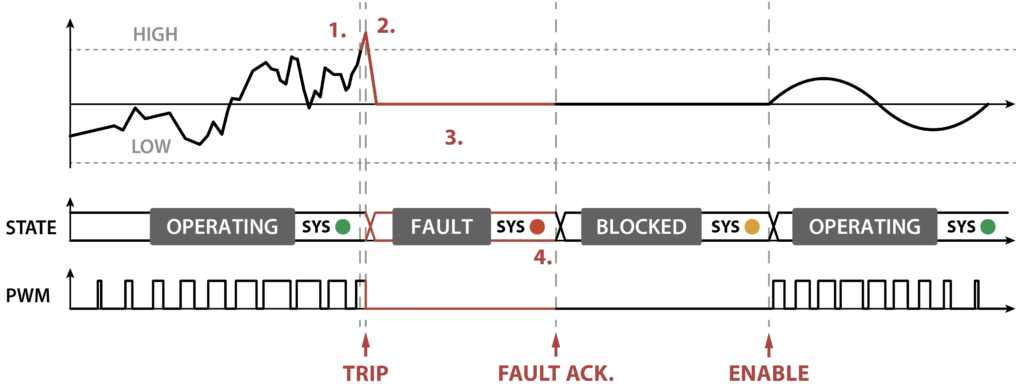
1. Fault is detected. The controller reacts almost instantly. An analog over-value fault is typically detected within 0.8 µs in the B-Box 4 (reaction times for other faults vary by controller and fault source). During this ultra-short interval, the fault current remains bounded to a reasonable value. The primary delay factor during this phase is the external sensor’s bandwidth.
2. Actual trip. All PWM outputs are instantly blocked, allowing the fault current to decay naturally based on the power stage inductance. GPOs remain unaffected unless explicitly configured otherwise within the software.
Concurrently, at the software level:
- The core state is switched to FAULT.
- A log message is displayed in Cockpit.
- The system (SYS) or CORE LED turns red.
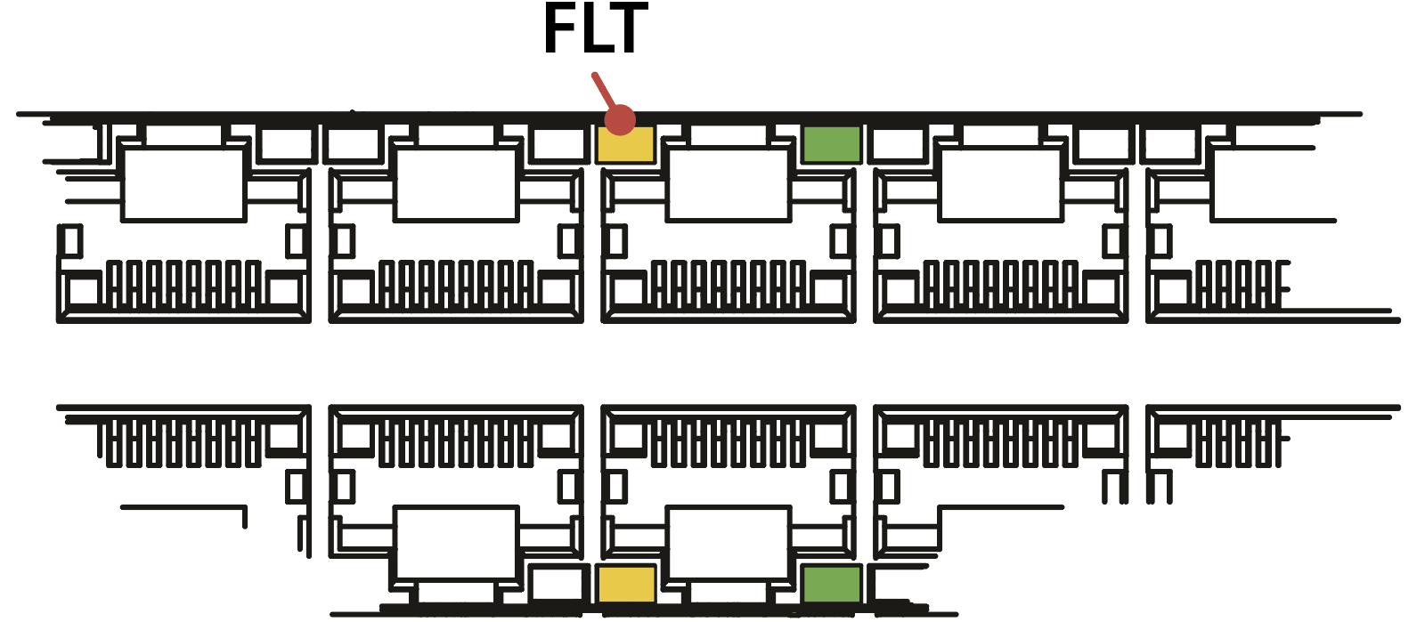
- If the fault was triggered by an analog input over-value, the orange LED on the faulty channel is turned on.
- For CPP SDK users, the routine UserError() is called, providing an opportunity to implement specific actions to be executed.
As long as the fault condition is present (e.g., the voltage or the temperature is too high), the fault cannot be acknowledged, and the operation cannot be resumed.
3. Fault condition disappearance. Three sequences are possible upon clearance of the fault:
- Most faults are automatically acknowledged (e.g., interlock line). Operation can be resumed immediately.
- Analog over-values must be manually acknowledged. Operation can only be resumed afterward.
- Software faults cannot be recovered from immediately. The user code must be restarted.
4. User acknowledgment. The fault should be acknowledged only after the user has clearly understood its root cause. Additionally, at the software level:
- The core state is switched to BLOCKED, meaning all PWM outputs remain blocked, but they can be re-enabled on demand.
- The system (SYS) or CORE LED turns orange.
- Any orange LED on analog inputs is turned off.
The whole sequence is summarized below:
Fault source types
A protection trip can be triggered by any of three possible source types:
- Hardware fault: Triggered at the hardware level, such as an analog measurement (voltage, current) exceeding its configured threshold. External fault flags (digital I/Os), such as on the interlock connector or VHDCI connectors, also induce so-called hardware faults.
- Software fault: Triggered at the kernel level to prevent unsafe CPU operation. The possible causes are either a software crash or an excessive execution time (overrun).
- User fault: Triggered intentionally by returning a fault flag from the user-level routines. By doing so, the user intentionally decides that safety mechanisms must be activated.
The following table lists the common fault sources:
| Cause | Available on | Type | Clear | Reason |
|---|---|---|---|---|
| Analog input over-value | B-Box only | Hardware | Manual ack. | Analog input exceeds the programmed safety limit |
| VHDCI fault lines | All except TPI | Hardware | Automatic | Active-low fault input from VHDCI ports |
| General FLT inputs | All except B-Box Micro, TPI | Hardware | Automatic | Active-high fault input from FLT ports |
| Interlock | All | Hardware | Automatic | Fault input from Interlock |
| RealSync | All except B-Box Micro | Hardware | Automatic | Fault propagated from other controllers inside the RealSync network |
| SOA | TPI only | Hardware | Automatic | Exceeding the TPI’s Safe Operating Area (SOA) |
| Watchdog | All | Software | Unrecoverable | CPU software crash |
| CPU overrun | All | Software | Unrecoverable | Unable to finish the CPU task within a control period |
| User-defined faults | All | User | Automatic | User-declared fault |
Protection trip sources
Hardware faults
Hardware faults can originate from five distinct sources:
a. Analog over-value protection
This critical safety feature protects the system by continuously comparing incoming analog signals against user-defined safety thresholds. If a threshold is violated, a trip signal is sent to the fault manager. The exact way this mechanism is implemented differs among the controllers. The reaction times and configuration methods differ too, as summarized in the table below:
| B-Box 4 | B-Box 3 (RCP) | B-Box micro | B-Board | TPI8032 | |
|---|---|---|---|---|---|
| Reaction time | 0.8 or 1.6 µs | 1.6 µs | 4.0µs | N/A | 4.0 µs |
| Configuration | On front panel or in Cockpit | On front panel | In Cockpit | N/A | Auto-computed Safe Operating Area (SOA) |
| User ack. | On front panel or in Cockpit | On front panel | In Cockpit | N/A | Automatic |
| Reference | PN252 | PN105 | PN106 | N/A | PN190 |
Additionally:
- PN257 provides general practical advice on configuring over-current and over-voltage protection, along with considerations for coordinating these protections with those present on imperix’s power modules.
- PN260 details the FPGA-level implementation of the analog input stage inside the B-Box 4.
b. VHDCI fault lines
Each VHDCI connector A, B, C, and D has one general fault input that is active-low and internally pulled up to 3.3 V via a 10 kΩ resistor. These inputs can be left floating when unused. More information is available in the devices’ datasheets.
c. General FLT inputs
These specialized active-high fault inputs are available on the VHDCI connectors A and B. Thanks to the optical expansion boards, these inputs are also compatible with optical feedback signals. The B-Box 4 provides 24 FLT inputs, and the B-Box 3 (RCP) and B-Board 3 (PRO) provide 16 FLT inputs. Other devices do not possess such inputs.
FLT inputs are disregarded by default. They can be enabled by instantiating the FLT block or calling the corresponding C/C++ configuration routine.
d. Interlock
All imperix controllers, except the B-Board PRO, feature an interlock input/output connector for emergency fault inputs or inter-device fault sharing. The interlock input is active-low and internally pulled down by default. Therefore, it must be shorted to the 5V supply or disabled when not in use.
To enable/disable the interlock from the B-Box front panel:
- Push the rotary button once to show the front panel menu.
- Rotate the button to select interlock, and push to enter the submenu.
- Rotate to switch between enabled and disabled, then push to save the configuration.

Hardware-related information about the interlock is given in the respective device datasheets.
e. Fault sharing over SPF/QSFP+ (RealSync)
In multi-controller setups connected via the imperix RealSync network, any fault is instantly propagated across the entire network with an ultra-low latency of 170 ns per hop (to the adjacent device). Furthermore, because RealSync operates over the Xilinx Aurora 8B/10B protocol, it benefits from its intrinsically robust data integrity mechanisms. On imperix controllers, any communication issue immediately generates a protection trip:
- Cyclic Redundancy Check (CRC): triggers a fault if any data frame is corrupted.
- Invalid code & disparity error: triggers a fault if the received 10-bit code doesn’t have the correct disparity or is invalid (not in the 8b/10b table).
- Link loss: triggers a fault if the communication link experiences a major disruption, such as loss of transceiver lock or a broken physical link.
More information on the operating principles and fault propagation mechanism of RealSync is given on PN264.
Software faults
To guarantee the safety and determinism of the hard real-time environment, the controller inherently monitors its own computational and communication integrity:
- Watchdog: triggers if the user code crashes or the FPGA fails to receive data from the CPU at the end of the control period.
- CPU overrun: triggers if the user app CPU fails to finish executing its interrupt within one interrupt period.
A software fault can cause unpredictable errors if the operation continues; these are considered unrecoverable. Therefore, the user code must be relaunched (at least).
User-defined faults
Additional faults can be declared by the user code using the User fault block or the corresponding C/C++ routine. For instance, in the Grid-Following Inverters (GFLIs) example, PWMs are shut down when the grid voltage drops below a certain threshold or when the grid synchronization is lost.
To go further
- Device-specific practical guidance for configuring the analog protection thresholds is given in PN257. The page also explains how these protections should be coordinated with other safety-related mechanisms (on-module protections, circuit breakers, etc.).
- PN261 further develops on the operating principles of imperix controllers in general, also addressing the devices’ architecture and their specificities.
Related Articles
Architecture of imperix controllers

Operating principles of imperix controllers
Over-current and over-voltage protection

Safety recommendations for working in the lab
