Table of Contents
This article describes the auto-identification feature for imperix’s latest current and voltage sensors — including those embedded in power modules — when used with the B-Box 4. This capability ensures true plug-and-play compatibility between the controller and its sensors, offering the following benefits:
- Mitigation of the risk of misconfiguration, thanks to detailed warnings in case of incorrect settings. Furthermore, the direct configuration of the safety limits in the sensor’s true value (e.g. Volts or Amperes) also contributes to reducing the risk of setting inadequate thresholds.
- Use of factory calibration data included inside the sensors for superior overall accuracy and precision.
Supported devices
Auto-identification is only possible from the newest imperix controller, namely the B-Box 4. On the sensor side, the supported devices are as follows:
| Product | Pre-calibrated offset | Pre-calibrated sensitivity | Comment |
|---|---|---|---|
| VSR-500-HBW | yes | no | |
| VSR-1000-ISO | yes | no | |
| CSR-25-HBW | yes | yes | |
| PEB-800-40 | yes | no | |
| PEN8018* | no | no | * Products > Q3 2026 |
Principles of operation
The necessary data for the auto-identification process is stored within an EEPROM located inside the sensors. This memory stores information on the sensor type as well as its calibration parameters (see table below), which the B-Box 4 can read or update using a dedicated pin inside the RJ45 cable (1-wire communication). This mechanism is slow and entirely independent of that of the measurement, whose data remains carried over a differential pair of analog signals.
| Parameter | Value example | User access from B-Box 4 |
|---|---|---|
| Sensor type | CSR-25-HBW | read only |
| Nominal sensitivity | 0.2 V/A | read only |
| Calibrated sensitivity | 0.199 V/A | read/write |
| Calibrated offset | 0.075 A | read/write |
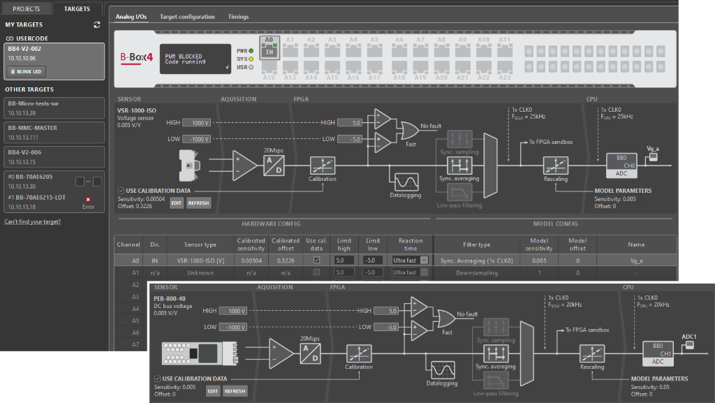
Communication via the 1-Wire link is active exclusively during the B-Box 4 startup sequence, when a user code is started, or upon manual initiation by the user via the refresh command. Upon completion of the reading cycle, the retrieved data is populated and available for review within the Analog I/Os tab of the Cockpit software.
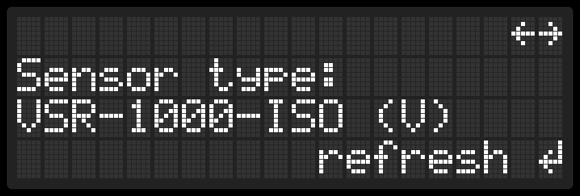
The same information is also accessible on the LCD screen of the B-Box 4‘s front panel. In the menu under ANALOG I/O and the corresponding channel, the display shows the name of the connected sensor. If needed, the user can initiate a manual refresh of the connected devices.
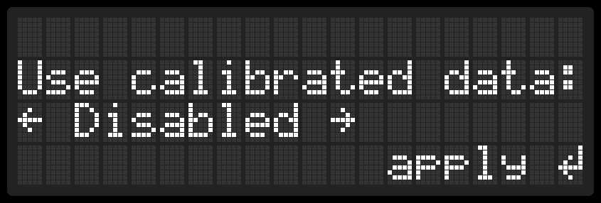
By default, calibration data is used in order to benefit from the related improvement of precision. However, if this is not desired for any reason, this option can be disabled either in Cockpit or using the front panel.
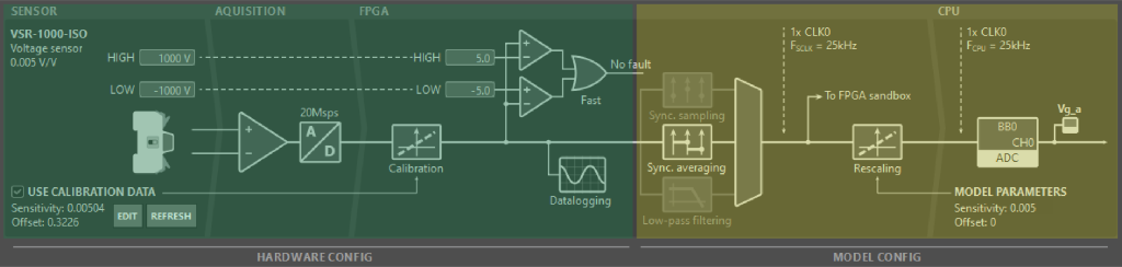
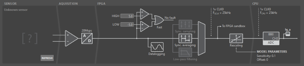
Coordination with analog channel parameters
Considering a complete analog I/O channel of B-Box 4, two parameter types should be distinguished:
- Hardware parameters (in green below) are stored on the hardware itself, namely the B-Box 4. Their configuration can be done using either Cockpit (Analog I/O tab) or through the front panel (LCD screen and button). These parameters are stored permanently, unless modified or reset. The safety limits as well as their reaction time are notable hardware parameters.
- Model parameters (in yellow below) are stored inside the Simulink/PLECS/C++ model. Their configuration must hence be done directly in the corresponding project files. These parameters are part of the control code (software), which are usually different for each project. The sampling method, as well as the re-scaling gain of the corresponding measurement, are notable model parameters.
More information regarding the configuration of the B-Box 4’s analog inputs is given in PN252.
Once a sensor is auto-identified, its associated characteristics (type, sensitivity, and offset) are stored as part of the corresponding hardware parameters. This enables the following functions:
- Hardware and model parameters are automatically and systematically compared, so that possible inconsistencies are identified.
- The sensitivity of the connected sensor is known with sufficient confidence so that the protection thresholds can be safely configured in true value (e.g., tens of amperes or hundreds of volts, at the sensor’s input) as opposed to a voltage on the ADC (e.g. few volts at most, at the sensor’s output).
Error messages and warnings
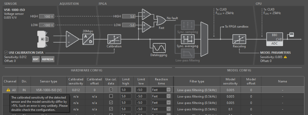
Several warnings may appear in Cockpit in relation to sensor auto-identification. These warnings, displayed in the Logs window and in the Analog I/Os tab, typically reveal probable misconfigurations, such as:
- The connected sensor type (model) differs from the one selected in the corresponding ADC block (if any).
- The sensitivity stored inside the detected sensor differs from that specified in the model (for that channel) by over 5%. This is unlikely to correspond to proper calibration, but rather indicates a wrong model configuration.
- A sensor is connected to a channel that is otherwise configured as an output, which doesn’t make sense.
Configuration of the safety limits
Another benefit of sensor auto-identification is that it simplifies the configuration of the safety limits and, consequently, reduces the risk of incorrect settings. For example, the safety limits for a CSR-25-HBW sensor or a PEB-800-40 module can be specified directly in amperes, so the user does not need to perform any conversion from the sensor’s output voltage. In this case, the safety limits can be set in the text fields just above the displayed sensor on the corresponding channel. They can also be set using the B-Box 4‘s front panel.
When auto-identification is not available, safety limits must, however, be set considering the sensor’s output voltage (i.e., the voltage applied to the ADC), rather than in the true measurement value.
More information about safety and protection is available in Over-current and over-voltage protection. Specific details about the configuration of the B-Box 4 are also given in PN252.
Factory calibration
Imperix products that are compatible with auto-identification (see table above) systematically undergo an offset calibration process, so that this information is identified and written to the EEPROM before shipping. This pre-calibration is expected to be vastly sufficient for most needs. Nonetheless, if recalibration is necessary for any reason, it can also be easily re-executed during use. A basic, yet typical process is presented below.
| Nominal sensitivity | Pre-calibration offset (= without auto-ID) Typ./Max. value | Post-calibration offset (= with auto-ID) Typ./Max. value | |
|---|---|---|---|
| VSR-500-HBW | 10mV/V | ±20mV / ±60mV | ±10mV / ±30mV |
| VSR-1000-ISO | 5mV/V | ±150mV / ±450mV | ±25mV / ±75mV |
| CSR-25-HBW | 200mV/A | ±90mA / ±270mA | ±20mA / ±60mA |
The sensitivity is factory pre-calibrated on the CSR-25-HBW. On the other devices, the sensitivity is not pre-calibrated, primarily for practical reasons. This parameter can nonetheless be updated afterwards, for instance, using the procedure described below.
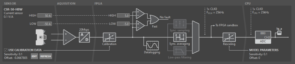
Manual offset calibration
To calibrate the offset, no other equipment than the sensor and the B-Box 4 is required.
Once confidence is gained that the measured value is truly zero, the following basic procedure describes how to identify and store offset-related information with minimum effort:
- Connect the sensor output to the desired ADC channel.
- In the Analog I/Os tab of Cockpit, select the corresponding analog channel.
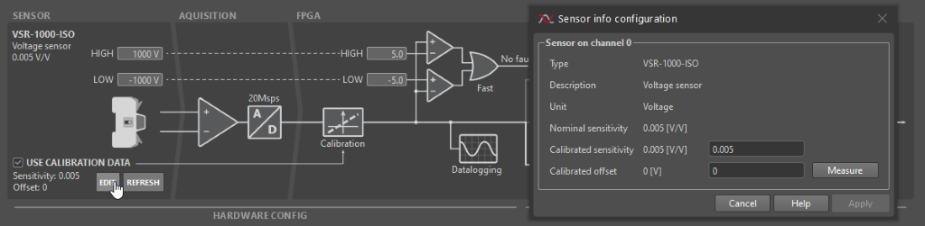
- Next to the displayed sensor, click on EDIT.
- In the sensor configuration pop-up, manually update the sensor offset (see image below).
- Click Apply to save the changes.
4. Click on Measure to launch an averaging measurement over 2s. The offset is automatically updated.
Manual sensitivity calibration
To correctly calibrate the sensitivity, a reference measurement provided by a higher precision device is required. A very basic, yet typical calibration procedure is described as follows:
- Make sure that the offset is properly calibrated first (see procedure above).
- Connect a precisely known voltage/current source to the sensor’s input, serving as the reference measurement. Note down that reference value.
- Observe the sensed value (e.g., using Cockpit). With the two results, calculate the new calibrated sensitivity:
$$S_{calibrated}=\frac{Val_{cockpit}}{Val_{reference}}\cdot S_{uncalibrated}$$ - In the sensor configuration pop-up, manually update the sensitivity.
– The calibration can only be as precise as the reference measurement, which is typically easier to achieve for a voltage than for a current.
– If reaching a high precision is possible and required, superior results can be obtained by making several (or numerous) points inside both the positive and negative sensor ranges, and deducing the offset and sensitivity using a least mean square linearisation method.