Table of Contents
This note describes the control of an adapted Siemens SINAMICS S120 active line module using the imperix B-Board PRO embedded control platform. With its low form factor and power-electronics-oriented interface, the B-Board PRO is well suited to laboratory, R&D, and prototyping environments where control algorithms must be deployed and evaluated early. Development time is reduced through the imperix automatic code generation toolchain, enabling rapid control prototyping on industrial-grade hardware. In this technical note, the SINAMICS S120 is operated as a grid-connected converter and extended with an external LC filter module.
B-Board PRO: The Embedded Control Platform
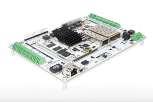
The B-Board PRO functions as the embedded controller for the converter system, enabling implementation of control algorithms in C/C++ or model‑based development via Simulink and PLECS. Typical applications for which B-Board PRO is optimized include industrial inverters and rectifiers, motor drives, multi-level inverters, and distributed control systems. Its high‑performance computational resources support control loop frequencies up to 200 kHz while preserving full firmware flexibility. The PWM outputs of the B-Board PRO have a resolution of 4 ns, which provides precision in controlling gate drivers. In addition, the imperix ACG SDK toolchain and the board’s firmware building blocks simplify implementation and reduce development time. This is achieved through features such as preconfigured PWM-modulation blocks, synchronous averaging, sampling aligned to the PWM carrier, fault management, and built‑in dead‑time handling. Pre-deployment verification can be performed in simulation and, if required, via hardware‑in‑the‑loop (HIL) testing before deploying the solution on the target power hardware.
Overall, B-Board PRO shortens the development cycle from initial design to experimental validation and, therefore, is an ideal choice as an embedded controller.
SINAMICS S120 Active Line Module
The SINAMICS S120 active line module from Siemens is a 16 kVA, three-phase, two-level, bidirectional converter, supplied in the booksize form factor. It is designed to operate as a regulated active front end, supporting both infeed operation (AC-to-DC) and regenerative feedback (DC-to-AC). For the customized variant used in this technical note, the power stage is driven by six gate signals (two per phase leg), which are available for external control. For feedback, the module provides four internal measurement channels. The main system specifications of the S120 are summarized in Table 1.
| Parameter | Value | Parameter | Value |
|---|---|---|---|
| Rated power (\(P_\mathrm{n}\)) | 16 kW | Peak infeed power (\(P_\mathrm{max}\)) | 35 kW |
| Line voltage (\(V_\mathrm{AC}\)) | 380…480 ± 10% | Line frequency (\(f_\mathrm{grid}\)) | 47…63 Hz |
| DC link voltage (\(V_\mathrm{DC}\)) | 510…720 V | Rated current @400V AC (\(I_\mathrm{AC}\)) | 25 A |
| DC link capacitance (\(C_\mathrm{DC}\)) | 705 µF | Rated switching frequency (\(f_\mathrm{sw}\)) | 8 kHz |
| Cooling method | Internal fan | Rated DC link current for 600V (\(I_\mathrm{DC}\)) | 27 A |
Interfacing B-Board PRO with SINAMICS S120
A customized carrier board was designed to interface the SINAMICS S120 converter with the B-Board PRO. This design leverages the principles detailed in PN201: Custom carrier board design for B-Board PRO. All control, protection, and digital measurement signals are routed between the converter and the B-Board PRO via the custom carrier board.
Custom carrier board design
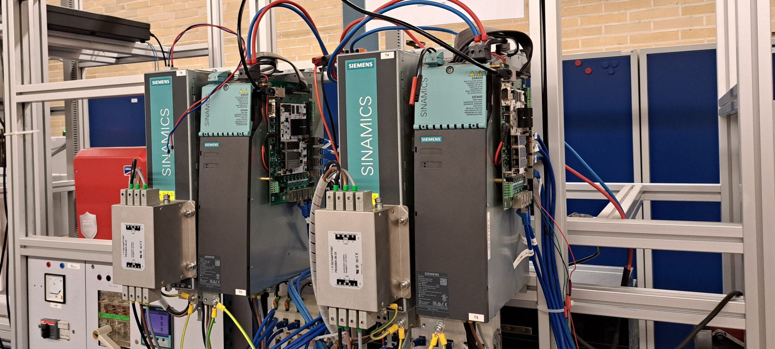
The interface connector of SINAMICS S120 exposes a set of control-related signals, including six PWM gate-driver signals, four measurement signals, precharge relay/ fan control, and temperature feedback for power-module monitoring. These signals are routed to the B-Board PRO through a connector on the integrated carrier board. An overview of the signals available on the box connector is provided in Table 2. The hardware setup is shown in Figure 1, where the B-Board PRO is mounted on a custom carrier board and assembled with SINAMICS S120.
| Type of signal | Signal name | Remarks |
|---|---|---|
| Gate signals for the three half-bridges | u_high, u_low, v_high, v_low, w_high, w_low | Connected to the PWM lanes of Board PRO |
| Clock and data signals from embedded delta-sigma modulators | clk_u, dat_u, clk_v, dat_v, clk_w, dat_w, clk_udc, dat_udc | Connected to the USR pins of the B-Board PRO. Used to sense output phase currents and DC link voltage. |
| Precharge relay and Fan activation signals | PRECHARGE, FAN | Connected to the GPIO pins of the B-Board PRO |
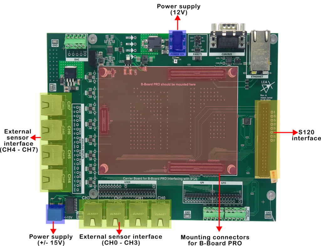
The assembled custom carrier board is shown in Figure 2. The following are the important interfaces on the carrier board:
- S120 interface (Yellow): A box connector connects directly to the modified S120 control port (signals are detailed in Table 2).
- External sensor interface (Green): RJ-45 connectors are routed to the eight ADC channels on the B-Board PRO. These sensor interfaces provide ±15V power to external imperix voltage/current sensors and route the analog signals back to the ADC.
- Power supply (Purple): The board requires a 12V input for the B-Board PRO and an external ±15V supply for the external imperix sensors.
- Mounting (Red): The B-Board PRO mounts on top of the carrier board via two high-speed 180-pin connectors (JX1 & JX2) and a 60-pin connector (JX3). For more information, please refer to the B-Board PRO datasheet.
Customized FPGA firmware design
The SINAMICS S120 system measures electrical quantities using delta-sigma (ΔΣ) ADCs. In this approach, each analog signal is processed by a ΔΣ modulator that generates a high-frequency 1-bit data stream. The measurement principle is based on oversampling and noise shaping, which shifts quantization noise to higher frequencies so that the low-frequency signal of interest can be recovered using a digital decimation filter, typically implemented as a sinc or cascaded integrator-comb (CIC) filter. Four embedded ΔΣ ADC modulators are used to measure the three output phase currents and the DC-link voltage. Further details on the operation of the delta-sigma modulator can be found here.
To make these ΔΣ measurements usable for control loops and protection functions, dedicated processing logic is implemented on the FPGA of the B-Board PRO. This platform is well suited for the application because its USR pins support data rates of up to 400 Mbps, enabling reliable acquisition and real-time decoding of the ΔΣ bitstreams with low latency, which is essential for fast hardware-based protection.
Delta-sigma decoding and data paths
The bitstreams of ΔΣ ADC measurements must be continuously filtered and decimated to a well-defined update rate synchronized to the PWM carrier. Because this requires processing tens of megabits per second across four ADC channels, too fast to handle directly on the CPU, the B‑Board PRO implements dedicated FPGA logic to perform the ΔΣ decoding and deliver time-aligned digital samples to the CPU, while also providing a deterministic data path and low-latency protection path independent of CPU execution time.
Each measured quantity from the S120 is transmitted as a pair of digital signals: a clock and a single-bit data stream. Four asynchronous delta-sigma decoder instances were integrated into the imperix FPGA firmware sandbox area using the Xilinx Vivado. The complete overview of the customized design is shown in Figure 3. Each decoder captures the data bitstream and performs digital filtering and decimation to generate scaled measurement samples. The decimated values are streamed to the CPU for control, while a parallel low-latency filter path exposes flag signals to the FLT for protection against faults. TN149 details the design and implementation of an FPGA-based decoder for a delta-sigma modulator. Each channel includes:
- A delta-sigma decoder based on cascaded sinc filters.
- A decimation stage that converts the high-rate bitstream into lower-rate sampled data.
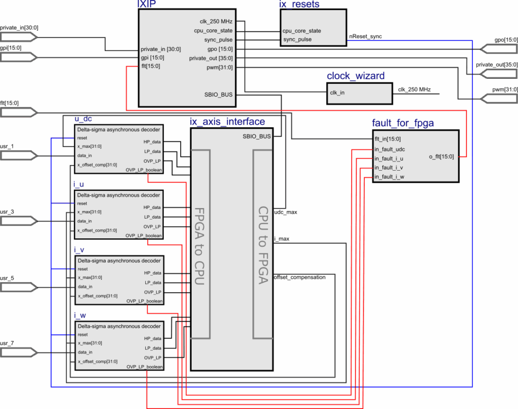
More information on how the FPGA of the B-Board PRO can be customized for different applications is provided in PN169.
Protection logic
To satisfy both control accuracy and fast fault reaction time, the FPGA logic processes the measurements through two parallel paths:
- High-Precision path (control): optimized for accuracy with moderate latency. This path has stronger filtering/decimation for control and monitoring.
- Low-Latency path (protection): optimized for minimum delay to support fast shutdown. This path has minimal filtering to detect threshold violations and trigger a rapid shutdown independent of CPU execution time.
Thresholds for overcurrent, overvoltage, and overtemperature are configurable at runtime via the imperix CPU↔FPGA data exchange interface (SBO for CPU→FPGA and SBI for FPGA→CPU). This allows protection limit adjustment from imperix Cockpit without FPGA recompilation. When a threshold is exceeded, the low-latecy path triggers the imperix fault management logic, which disables PWM and forces the outputs into a defined safe FAULT state.
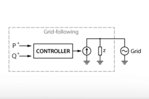
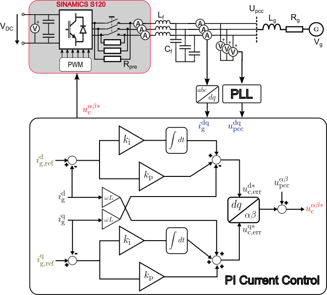
Control of the grid-following converter
In this application example, the SINAMICS S120 is operated as a grid-following voltage source converter connected to a stiff distribution grid. Detailed analysis of the operation and control of a grid-following converter is provided in TN167. In this mode, the converter relies on the grid to set voltage and frequency and regulates only the exchange of active and reactive power. Synchronization with the grid voltage is achieved by estimating its phase and frequency, using a synchronous reference frame PLL. Therefore, the grid-following converter acts as a controlled current source. In this implementation, active and reactive power flow is directly controlled by the current references: \(i_\mathrm{g,d}\) (\(i_\mathrm{g,d} \propto P\)) and \(i_\mathrm{g,q}\) (\(i_\mathrm{g,q} \propto Q\)), using the vector current control in the dq reference domain.
As shown in Figure 4, the design of the current controller requires a total of seven measurement signals. Additionally, the SINAMICS S120 features precharge resistors that enable the safe charging of DC link capacitors during startup, thereby limiting inrush currents. The DC link precharge relay is used to bypass the precharge resistors. Further details on DC link precharging principles and implementation are provided in TN131.
Software Implementation
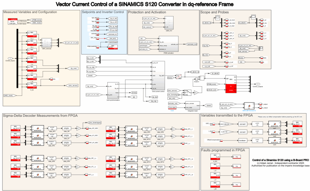
The control algorithm for the control of SINAMICS S120 as a grid-following converter has been designed, simulated, and tested using MATLAB Simulink and imperix ACG SDK, as shown in Figure 5. The SINAMICS S120, the LC filter, and the grid were modelled in Simulink using blocks from Simscape for offline simulation and verification of the controller’s operation. The code was generated automatically using imperix ACG SDK toolchain. In this note, a PWM enabling mechanism and a protection mechanism have also been implemented.
PWM enabling mechanism
The software verifies the following conditions before enabling PWM signals:
- The precharge resistor for DC link precharging has been bypassed.
- Three-phase voltage levels at PCC exceed the minimum grid voltage to verify the presence of grid, \(V_\mathrm{g,min}\) , set by the user. \(V_\mathrm{g,min}\) can be selected as 20% of the nominal grid phase voltage.
- The grid angular frequency lies within the permissible range, \([\omega_\mathrm{min},\omega_\mathrm{max}]\). The typical values for \([\omega_\mathrm{min},\omega_\mathrm{max}]\) can be set as ±5% of the nominal grid angular frequency.
If any of these conditions is not satisfied, PWM remains blocked, and the state machine transitions to the BLOCKED state.
Two-layer protection mechanism
The designed converter system employs a two-layer protection mechanism to ensure safe operation under fault conditions. When a fault condition is detected, regardless of CPU activity, the following happens:
- PWM outputs are immediately disabled at the hardware level.
- The system is forced into a safe FAULT state.
- A corresponding fault signal is asserted.
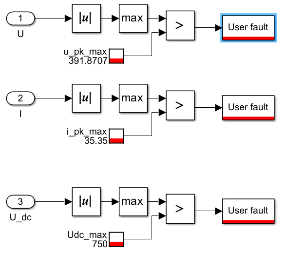
1- Software protection
The first protection layer is implemented in software and operates at the CPU control frequency. It is realized in the C-code automatically generated from Simulink (see Figure 6). If any of the following parameters: DC link voltage, the three output phase voltages, and the three output phase currents of the S120 converter, violate the user-defined limits, the software triggers a “User Fault,” transitioning the state machine to FAULT state and blocking PWM. This protects against steady-state violations or slow thermal drifts.
2- FPGA protection
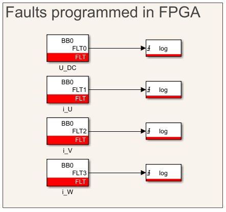
The second protection layer is implemented directly in the FPGA firmware, enabling faster fault detection and reaction independent of the control software or CPU. It provides critical protection against short circuits or high di/dt overcurrents. It utilizes the low-latency data path described in Section 4. If the delta-sigma decoder output exceeds the hardware threshold, the imperix fault logic disables the PWM signals within microseconds. Activation of this hardware protection is configured via FLT block in the control software, as shown in Figure 7, while the fault detection and reaction itself remain fully hardware-based.
Experimental Results
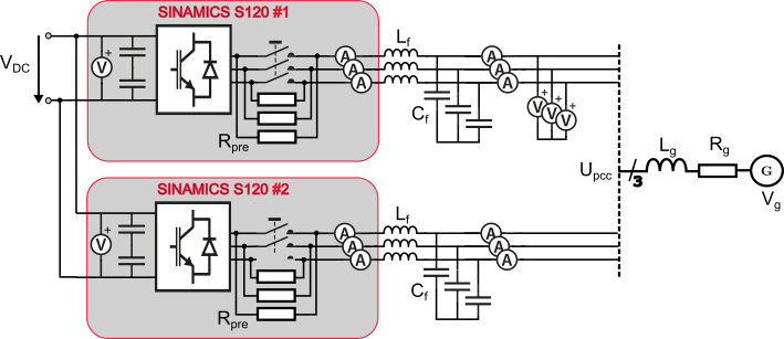
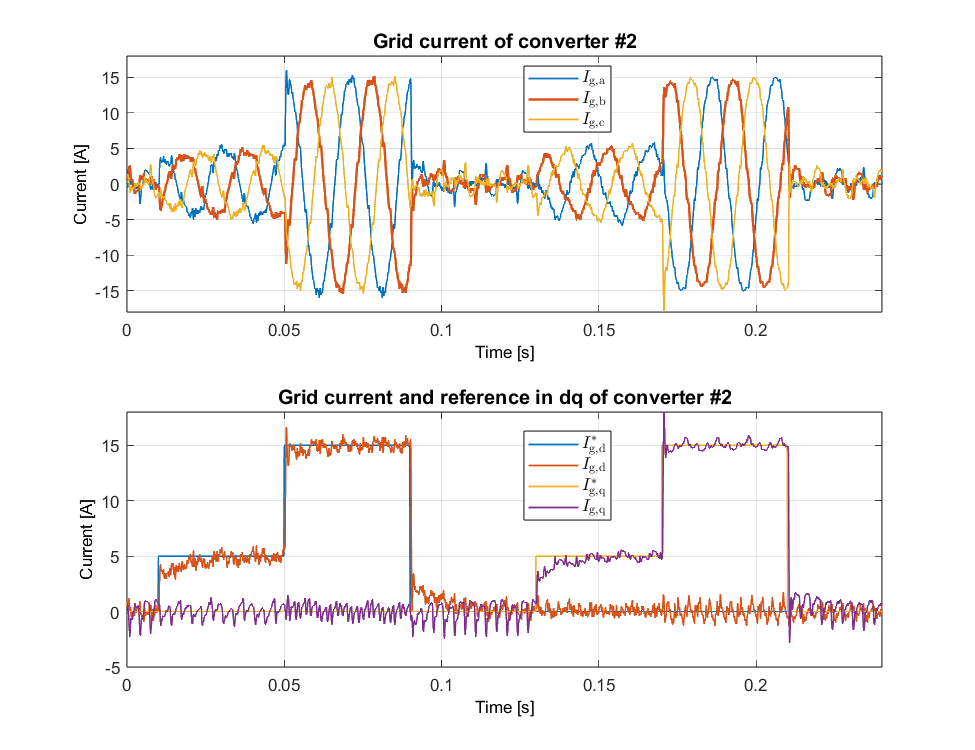
The experimental setup is shown in Figure 8, which consists of two SINAMICS S120 converters tied to a common DC link, effectively doubling the DC link capacitance. Each converter connects to the PCC through an LC filter, which is schematically represented in Figure 9. The experiments validate correct synchronization, current control performance, and parallel operation capability (e.g., master-master or master-slave ) via imperix RealSync.
In this case, both converters used the same grid-following current controller design and gains, configured as a master–slave system, with the two B-Board PROs interconnected via a high-speed SFP link. This link synchronizes the PWM time bases, ensuring simultaneous switching events with a 4 ns PWM timing resolution, which is essential for avoiding circulating currents and achieving stable current sharing when operating converters in parallel.
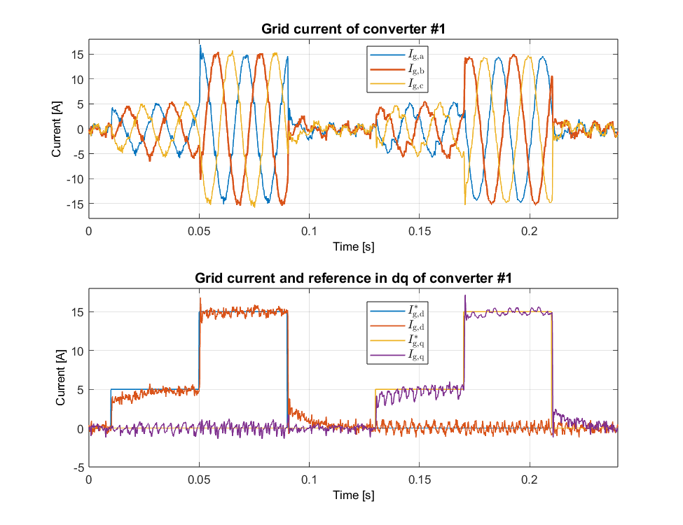
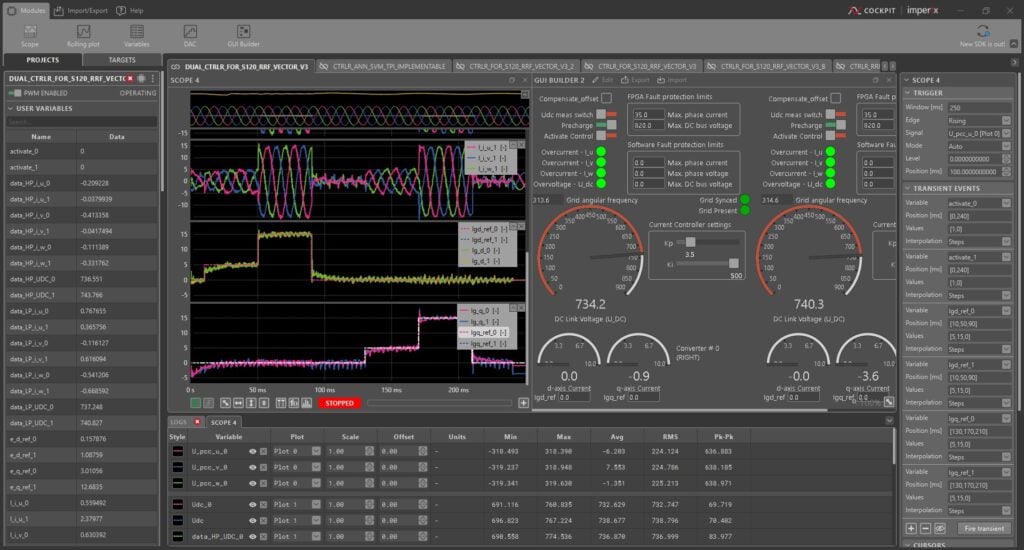
In this configuration, the DC voltage is supplied by an external DC source of \(750 V\), and the switching frequency is set to 8 kHz. The controller is tuned for a fast dynamic response. The measured results for converters #1 and #2 (Figure 10 and Figure 11) confirm stable operation: the three-phase grid currents are well balanced without any sudden jumps, and the d-axis and q-axis currents closely follow their references, exhibiting comparable dynamics on both converters. A dedicated Cockpit GUI was developed for coordinated operation and monitoring of both converters, as shown in Figure 12.
General tips for B-Board PRO interfacing
When interfacing the B-Board PRO with third-party power converters or power modules, careful attention must be paid to signal compatibility, protection integration, and timing requirements.
- Logic-level compatibility of PWM, enable, and fault signals should be verified, and appropriate level shifting or signal conditioning must be added on the carrier board if required.
- The B-Board PRO outputs PWM signals assuming active-high logic (a high level turns on the semiconductor). It is therefore essential to confirm whether the target gate driver or power module expects active-high or active-low PWM inputs. External pull-ups or pull-downs may be required on some pins to enforce a known default condition before the PWM becomes active.
- Fast protection signals from the power module, such as overcurrent, should be routed directly to the imperix firmware IP fault inputs inside the FPGA design to ensure fast shutdown independent of CPU execution.
- ADC input channels of B-Board PRO must be adapted to the analog sensor output, with particular care taken to match the voltage range, bandwidth, and isolation requirements of current and voltage feedback signals.
- Thermal and voltage/power derating limits should be enforced at the control level. Even if the power module includes internal protection, implementing software-level limits improves robustness.
- Proper grounding and isolation should be ensured to avoid noise coupling and ensure reliable operation when the B-Board PRO is integrated with the converter hardware.
Conclusion
This technical note demonstrates the utility of using imperix B-Board PRO embedded control platform with an industrial-grade SINAMICS S120 converter. Any industrial or reference design converter can be interfaced with B-Board PRO if access to the gate signals, fault signals, and embedded sensors is provided through an interface. It has been shown that:
It can be concluded that using imperix ACG SDK with model-based workflows (Simulink/PLECS) significantly shortens the path from controller design concept to real-time implementation and experiments on hardware.
Acknowledgements
The author would like to thank the Institute of Power Electronics and Control of Drives (LEA) at the Technical University of Darmstadt, Siemens AG, and imperix for their continued support throughout the successful completion of this project. This work was funded by the German Federal Ministry of Education and Research (BMBF).
To go further from here:
Please check out PN205 for the detailed custom design of the carrier board for hosting B-Board PRO. Furthermore, the following resources might also be interesting for the control of grid-connected converters:
TN167: Grid-following Converter
TN168: Grid-forming Converter
TN166: Active Front End (AFE)