Table of Contents
This application note details a technique for the DC bus pre-charge of a grid-tied inverter from the AC mains. This method is standard practice within imperix power converter systems. Additionally, the note addresses appropriate solutions for discharging the power converter, ensuring a complete operational procedure.
Why pre-charging the DC bus of an inverter?
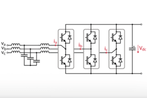
Nowadays, Voltage Source Converter (VSCs) are widely used in grid-tied applications. They indeed offer several benefits over Current Source Converters (CSCs), such as reduced filtering requirements, superior efficiency and easier use in weak grid conditions.
However, VSCs impose that the DC bus voltage is kept higher than the rectified AC voltage \(V_r\) at all times. This is indeed essential to avoid uncontrollable current flows through the converter diodes. Besides, this condition is also required by the converter’s own protection mechanism, which assumes that the blocking of all its PWM signals yields rapidly vanishing currents.
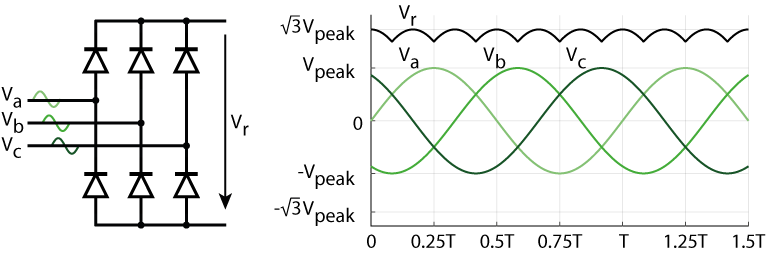
As such, VSCs impose to make sure that the DC bus is appropriately pre-charged before normal operation can be initiated. The corresponding condition is \(V_{DC,min}=\sqrt{3}{V_{peak}}\).
– Very easy to achieve with an independently-controlled DC bus voltage, e.g. using a properly configured reversible DC power supply. The DC voltage only requires to be high enough.
– Inevitable – due to passive rectification – once grid connection has been made and after steady-state conditions have been met, even briefly.
– Not necessarily true in other conditions.
Pre-charge circuit description
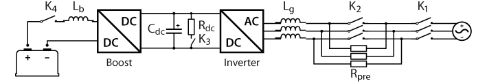
In order to appropriately raise the DC bus voltage before the operation, a pre-charge circuit can be introduced between the converter and the grid, for instance made of a three-phase set of resistors. These resistors can be later bypassed during normal operation, thanks to a software-controlled relay. The figure below shows the corresponding circuit.
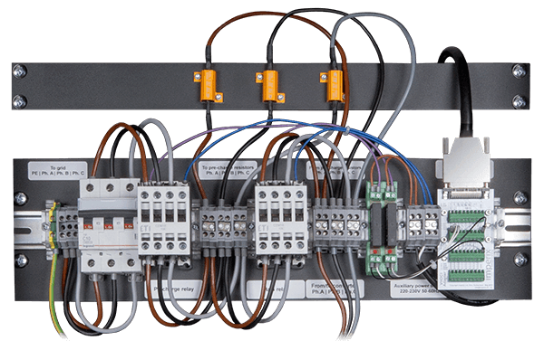
One way of implementing that AC pre-charge circuit is by using imperix’s handy grid connection panel. It includes the three current-limiting resistors and the two relays (controllable from a B-Box controller), as well as an additional circuit breaker.
Principle of operation
Pre-charge of the inverter DC bus
When the converter is not switching and its DC bus is not charged, all contactors are open. This corresponds to the standby situation.
To pre-charge the DC bus, the first step is to close the contactor K1: then, the converter is connected to the AC grid through the resistors, which limit the current flowing from the grid. The maximal current flowing into the DC bus capacitor can be expressed as:
$$\begin{array}{l}\displaystyle I_{max} = \displaystyle\frac{\sqrt{3}V_{peak}}{2 R_{pre}}\end{array}$$
The second step consists of closing the contactor K2. Then, the converter is closely tied to the grid and operates normally. The precharge resistors are short-circuited and have no impact on the converter’s operation. The converter can now be enabled.
Discharge of the inverter DC bus
To discharge the DC bus, first disable the PWM signals. Then, open all contactors to isolate the bus. Finally, a third contactor connected to a resistive load on the DC bus can be closed. The current flowing from the capacitor(s) into the resistance can be expressed as:
$$\begin{array}{l}\displaystyle I_{max} = V_{dc}/R_{dc}\end{array}$$
The corresponding discharge time can be expressed as:
$$\begin{array}{l}\displaystyle t_{dis} = 3\cdot\tau=3\cdot R_{dc}\cdot C_{dc}\end{array}$$
Another option consists in re-activating the converter after all contactors are open in order to generate sufficient switching losses so that the discharge of the DC bus is accelerated.
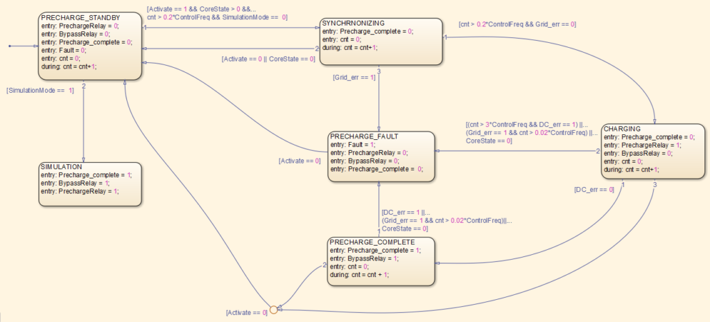
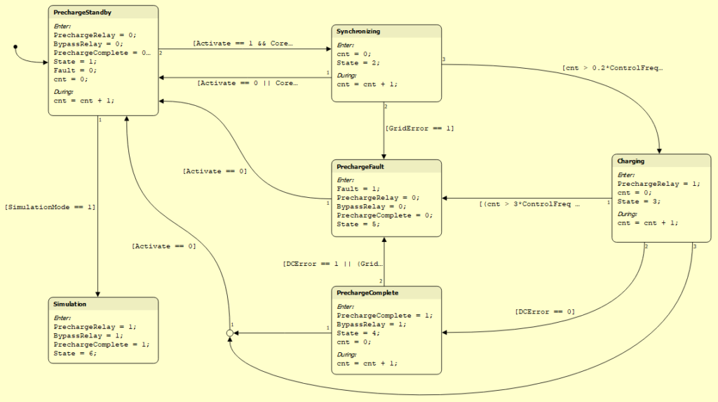
State machine implementation
As already explained, the order of opening/closing contactors is key to avoid potentially damaging currents . It is also important to take into account the time that each contactor requires for its operation.
For this purpose, the implementation of a state machine is recommended. This also facilitates the grid connection/disconnection procedures, thanks to automated mechanisms. The following shows the implementation of a state machine in C++, Simulink, and PLECS, notably used in AN006.
C or C++ implementation of a DC-bus pre-charge
void User_RunPrechargeFSM()
{
	/**
	 * This state machine controls the precharge of the DC bus.
	 * The user can switch the input "activate" between 1 and 0 to respectively start/stop the precharge.
	 * The state machine waits at least 250ms between the "CHARGING" and "CLOSING_BYPASS_RELAY" states.
	 * It also waits 200ms between the "CLOSING_BYPASS_RELAY" and "READY_TO_OPERATE" states, because the bypass relay needs a few millisecond to close.
	 * The output "Ready" indicates that the bus is precharged and the converter is ready to operate.
	 * If a fault occurs (CoreState is 0), the state machine goes in "DISCHARGING" state and opens all the relays for security.
	 * In simulation, the state machine goes in "SIMULATION" state, to avoid the simulation of the whole precharge. The user still can set the variable "SimulationMode" to 0 in order to simulate the precharge.
	*/
	switch (Next_state_precharge){
	// Init
	case PRECHARGE_INIT:
		State_precharge = PRECHARGE_INIT;
		Next_state_precharge = PRECHARGE_STANDBY;
		break;

	// The converter is disconnected from the grid and is in standby, all the relays are open
	case PRECHARGE_STANDBY:
		if (State_precharge != Next_state_precharge)
			Log_SendMsg(0, NULL, 0);
		State_precharge = Next_state_precharge;

		precharge_relay = 0;
		bypass_relay = 0;
		Precharge_ready = false;
		Precharge_fault = false;
		if (State_precharge != Next_state_precharge)
			precharge_cnt = 0;
		else
			precharge_cnt++;

		if (activate == 1 && core_state > 0 && precharge_cnt > 0.2*SW_FREQ)
		{
			Next_state_precharge = SYNCHRONIZING;
		}

		break;

	// The converter is synchronizing to the grid
	case SYNCHRONIZING:
		if (State_precharge != Next_state_precharge)
		{
			Log_SendMsg(1, NULL, 0);
			precharge_cnt = 0;
		}
		else
		{
			precharge_cnt++;
		}
		State_precharge = Next_state_precharge;

		Precharge_ready = false;
		Precharge_fault = false;
		precharge_relay = 0;
		bypass_relay = 0;


		if (precharge_cnt > 0.2*SW_FREQ && !err_No_GridSync && !err_No_Grid && core_state != 0)
		{
			Next_state_precharge = CHARGING;
		}
		else if(activate == 0 || core_state == 0)
		{
			Next_state_precharge = PRECHARGE_STANDBY;
		}
		else if(err_No_GridSync || err_No_Grid)
		{
			Next_state_precharge = PRECHARGE_FAULT;
		}

		break;

	// The DC bus of the converter is being charged from the grid (precharge relay closed)
	case CHARGING:
		if (State_precharge != Next_state_precharge)
		{
			Log_SendMsg(2, NULL, 0);
			precharge_cnt = 0;
		}
		else
		{
			precharge_cnt++;
		}
		State_precharge = Next_state_precharge;

		Precharge_ready = false;
		Precharge_fault = false;
		precharge_relay = 1;
		bypass_relay = 0;

		if (!err_Vpv_low && !err_Vpv_high && !err_Vdc_low && !err_Vdc_high)
		{
			Next_state_precharge = PRECHARGE_COMPLETE;
		}
		else if ((precharge_cnt > 3*SW_FREQ && (err_Vpv_low || err_Vpv_high || err_Vdc_low || err_Vdc_high)) || (precharge_cnt > 0.02*SW_FREQ && (err_No_GridSync || err_No_Grid)) || core_state == 0)
		{
			Next_state_precharge = PRECHARGE_FAULT;
		}
		else if (activate == 0)
		{
			Next_state_precharge = PRECHARGE_STANDBY;
		}

		break;

	// The DC bus is precharged and the converter is fully connected to the grid (bypass relay closed)
	case PRECHARGE_COMPLETE:
		if (State_precharge != Next_state_precharge)
			Log_SendMsg(3, NULL, 0);
		State_precharge = Next_state_precharge;

		precharge_relay = 1;
		bypass_relay = 1;
		Precharge_ready = true;
		Precharge_fault = false;

		if (err_Vpv_low || err_Vpv_high || err_Vdc_low || err_Vdc_high || (precharge_cnt > 0.02*SW_FREQ && (err_No_GridSync || err_No_Grid)) || core_state == 0)
		{
			Next_state_precharge = PRECHARGE_FAULT;
		}
		else if(activate == 0)
		{
			Next_state_precharge = PRECHARGE_STANDBY;
		}

		break;

	// A fault occurred during the precharge procedure, all the relays are open
	case PRECHARGE_FAULT:
		if (State_precharge != Next_state_precharge)
			Log_SendMsg(4, NULL, 0);
		State_precharge = Next_state_precharge;

		precharge_relay = 0;
		bypass_relay = 0;
		Precharge_ready = false;
		Precharge_fault = true;

		if(activate == 0)
		{
			Next_state_precharge = PRECHARGE_STANDBY;
		}

		break;
	}

	state_precharge_uint = (unsigned int) State_precharge;
}Code language: C++ (cpp)
Other applications
The same DC-bus precharge technique can be used for other grid-connected voltage-source inverter topologies. This also includes multi-level topologies such as cascaded H-bridges (TN165), which can be used in higher voltage applications such as solid-state transformers (AN015).