Table of Contents
This note presents several modulation techniques to operate a Dual Active Bridge (DAB) converter. First, the topology and the theoretical aspects of the Dual Active Bridge converters are presented, including a short overview of the main modulation techniques. Then, a possible control implementation on the B-Box RCP or B-Board PRO is introduced using ACG SDK on Simulink, and simulation results are shown.
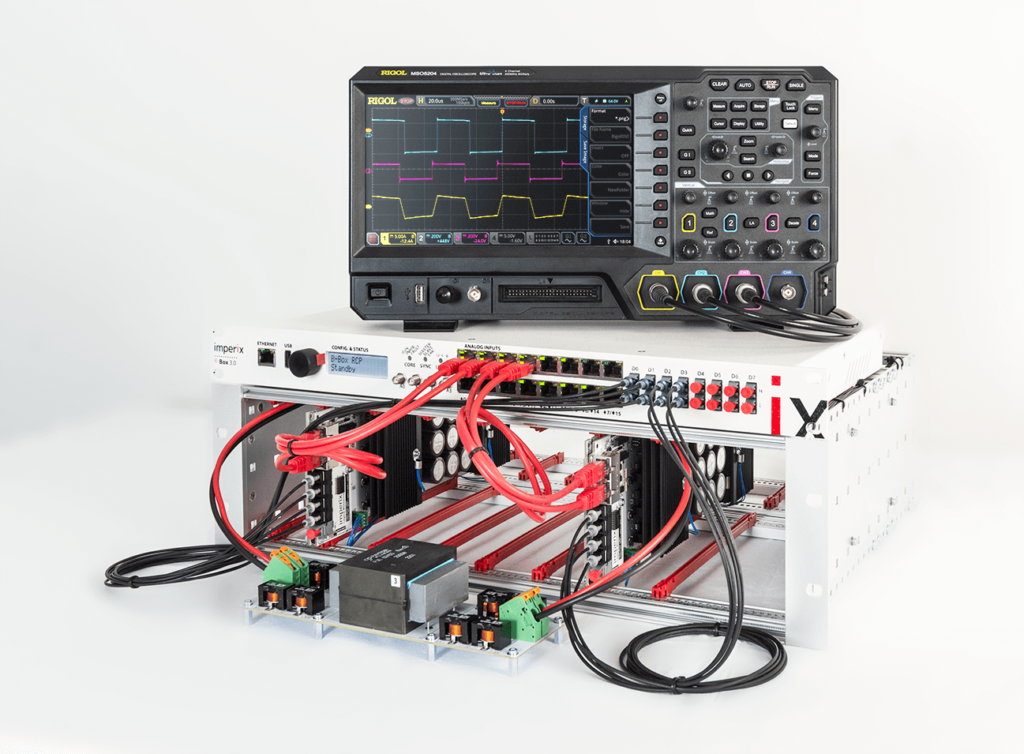
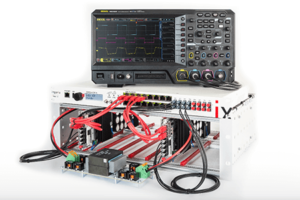
A Dual Active Bridge converter prototype (image below) and its control are presented in more detail in DAB converter control.
Dual Active Bridge converter overview
A Dual Active Bridge is a DC/DC converter offering galvanic isolation and bidirectional power flow. The galvanic isolation is ensured by a high-frequency intermediary transformer.
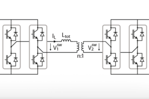
The topology of the dual active bridge converter is shown in the following figure. This system can be easily implemented using four PEB modules, or two PEH modules.
The power transfer inductance \(L_{tot}\) is the sum of the transformer leakage inductance and any additional inductance placed at the primary or secondary of the transformer.
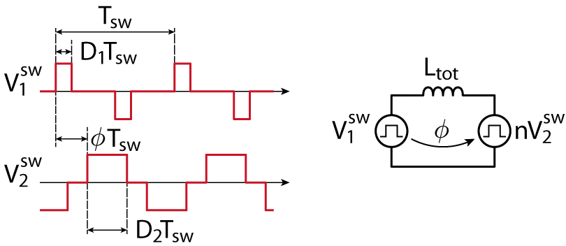
The simplified loss-less scheme of the Dual Active Bridge converter is shown below. It assumes that the magnetizing inductance is infinite, the switches and the voltage sources are ideal, and neglects the winding resistance and capacitance.
The simplified model above shows that the power transfer between the primary and secondary sides is mainly governed by the current through the inductance \(L_{tot}\), which, in turn, derives from the voltage across the inductor \(V^{sw}_2-V^{sw}_1\). Therefore, a power flow control can be achieved by acting on the parameters defining the voltage across the inductor, namely:
- The duty-cycle \(D_1\) of the 3-level switched voltage \(V^{sw}_1\)
- The duty-cycle \(D_2\) of the 3-level switched voltage \(V^{sw}_2\)
- The phase-shift \(\phi\) between \(V^{sw}_1\) and \(V^{sw}_2\), relatively to the switching period \(T_{sw}\)
- The switching frequency \(f_{sw}\) of \(V^{sw}_1\) and \(V^{sw}_2\) (although generally kept constant)
Although all 3 degrees of freedom can be combined and exploited in an optimization process, the most used method is to fix some of the parameters to reduce the problem complexity. This leads to 3 typical modulation techniques of different complexity, achieving different levels of performance.
Modulation techniques for Dual Active Bridge converters
The principal modulation techniques traditionally used are the 1) phase-shift, 2) triangular and 3) trapezoidal modulations. These techniques may also be 4) combined.
Phase-shift modulation
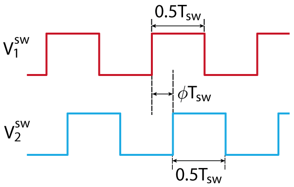
Phase-shift modulation is probably the simplest modulation technique for dual active bridge converters. It uses \(D_1=D_2=0.5\) (i.e. 2-level switched voltages), reducing the degrees of freedom to \(\phi\) only.
The switched voltage and inductor current waveforms are depicted below:
With this method, the power transfer between the primary and secondary has the following simple expression and has a maximum for \(\phi=0.25\).
$$ P = \displaystyle\frac{nV_1 V_2}{f_{sw}L_{tot}}\phi(1-2\phi) $$
Some of the benefits and drawbacks of this method are summarized in the following table:
| Benefits | Drawbacks |
|---|---|
| Simplicity (1-D of freedom) | Higher RMS transformer current |
| Highest achievable power flow | Limited operating range with low switching losses |
Due to a high RMS current (hence conduction losses), and high switching losses, phase-shift modulation cannot be used for high-efficiency applications. Nevertheless, the best ratio between transferred power and inductor RMS current is optimal when \(V_1=nV_2\), making phase-shift modulation attractive when operated close to that operating point.
Triangular modulation
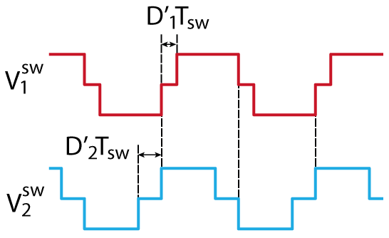
In triangular modulation, 3-level switched voltage waveforms are generated by both the primary and the secondary H-bridges. The waveforms (see graph below) are such that the beginning of their pulses is aligned, and the secondary is switched off as soon as the inductor current reaches zero. In this case, the secondary H-bridge switches always under zero current (ZCS).
The condition for ZCS of the secondary is \((V_1-nV_2)D_1=nV_2(D_2-D_1) \Rightarrow V_1 D_1=nV_2 D_2 \). This also implies that no power transfer is possible when \(V_1=nV_2\).
More generally, it can be shown that for \(V_1>nV_2\) , the power transfer is limited to
$$ P_{max}^{tri}=\displaystyle\frac{n^2 V_2^2 (V_1-nV_2)}{4f_{sw}L_{tot}V_1} $$
Some of the benefits and drawbacks of this method are summarized in the following table:
| Benefits | Drawbacks |
|---|---|
| Secondary always switches under zero current | Increased complexity |
| Reduced RMS transformer current | Power transfer direction defined by voltage difference |
| Allows better converter efficiency | Limited achievable power flow (particularly when close to \(V_1=nV_2\)) |
Trapezoidal modulation
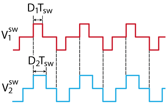
The limited maximum power transfer of triangular modulation can be increased by using trapezoidal modulation. With this technique, ZCS is achieved twice per period on both the primary and secondary H-bridges. Typical waveforms are shown below.
The condition for ZCS at applicable times on primary and secondary sides is still \(V_1D_1=nV_2D_2\).
It can be shown that:
$$ P_{max}^{tra}=\displaystyle\frac{n^2V_1^2V_2^2}{4f_{sw}L_{tot}(V_1^2+nV_1V_2+n^2V_2^2)} > P_{max}^{tri} $$
Some of the benefits and drawbacks of this method are summarized in the following table:
| Benefits | Drawbacks |
|---|---|
| Higher achievable power than triangular | Cannot be applied for low power transfer |
| Still ZCS on some switching | Not always ZCS on the secondary |
Combined modulation
For optimal converter efficiency over a large range of power, a combination of techniques can be used. In particular, a seamless transition between triangular and trapezoidal modulation can be achieved when the inductor current is zero. This allows benefiting from the high efficiency of triangular modulation at low power, and the higher power capabilities of trapezoidal modulation when required.
References on dual active bridge converters
- F. Krismer, “Modeling and Optimization of Bidirectional Dual Active Bridge DC-DC Converter Topologies,” Ph.D. dissertation, ETH Zurich, 2010
- F. Jauch and J Biela, “Generalized Modeling and Optimization of a Bidirectional Dual Active Bridge DC-DC Converter Including Frequency Variation,” in IEEJ Journal of Ind. Appl., Vol. 4, N° 5, 2015, pp. 593-601
Dual active bridge control example
Software resources
The Simulink demo model can be downloaded below. It can be used for Simulink-based simulation or code generation for real-time execution on imperix controllers.
Variable-phase PWM modulator
Thanks to the flexible Carrier-Based PWM modulator provided with imperix’s library (CB-PWM), control over the duty-cycle and the phase-shift of the PWM signals can be achieved very easily:
With imperix CPP SDK
Configuration:
CbPwm_ConfigureClock(PWM_CHANNEL_0, CLOCK_0);Update:
CbPwm_SetDutyCycle(PWM_CHANNEL_0, dutyCycle);
CbPwm_SetPhase(PWM_CHANNEL_0, phase);
Phase-shift modulation using Simulink
In phase-shift modulation, the switched waveforms \(V^{sw}_1\) and \(V^{sw}_2\) must be 2-level, i.e. \(D_1=D_2=0.5\). In order to generate them from the primary and secondary H-bridges, the switching state of each of the 8 transistors can be obtained with a Carrier-Based PWM modulator (CB-PWM), using the following configuration:
With Dual Active Bridge converters, one can be interested in controlling the secondary voltage to a fixed value. A simple way of achieving that is by acting on the angle \(\phi\) to control the power transfer to charge/discharge the secondary DC bus to the desired voltage.
In a possible implementation depicted below, PI controller regulates the secondary voltage at the desired value by generating a phase-shift reference. In addition, a feedforward term can be added to the phase-shift reference for improved dynamics. In the case of phase-shift modulation, the required angle can be derived from the power transfer equation, considering \(P^*\) the required power to achieve the desired output voltage \(V^*_2\) on the load resistor \(R_{out}\):
$$ P^*=\displaystyle\frac{{V^*_2}^2}{R_{out}} \Rightarrow \phi = \displaystyle\frac{1}{4}\left(1-\sqrt{1-\frac{8f_{sw}L_{tot}V^*_2}{nV_1R_{out}}}\right) $$
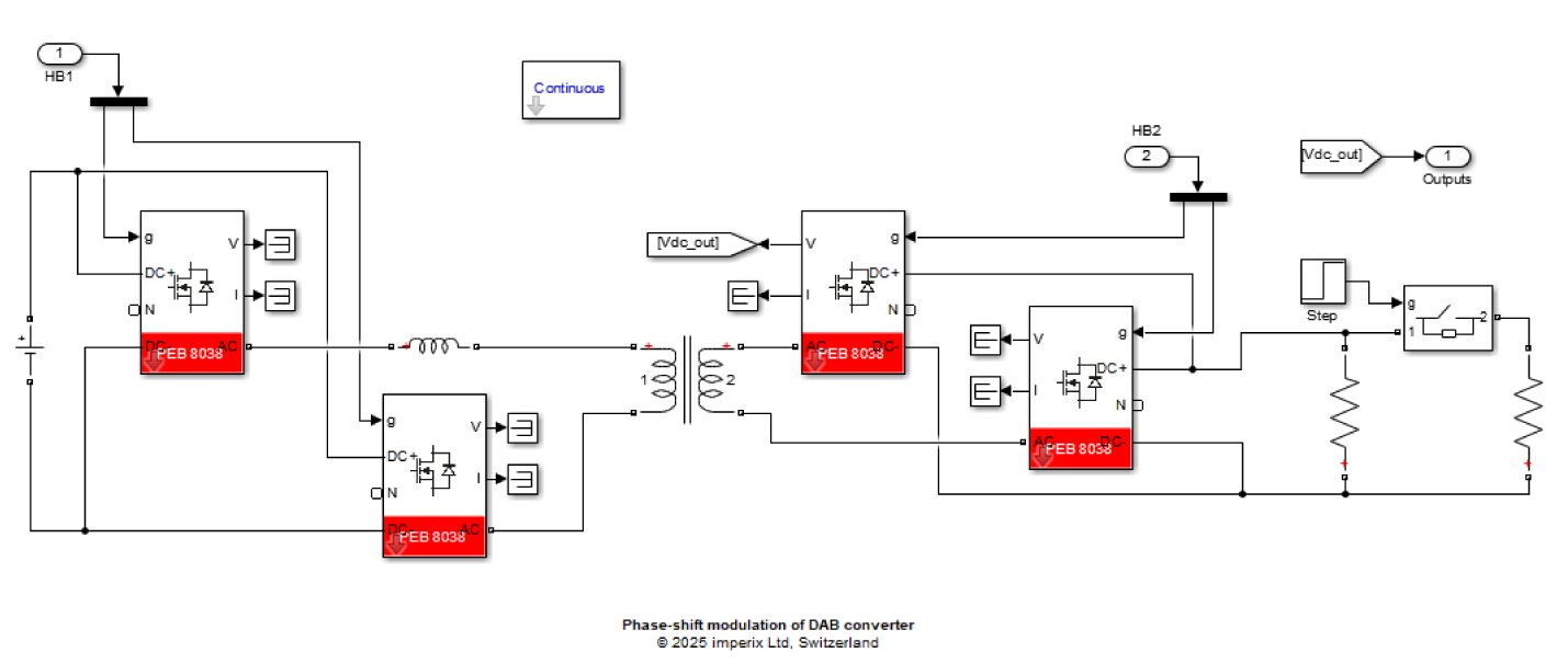
Thanks to imperix ACG SDK, this control implementation can be tested using offline simulation. The corresponding results are presented in the next section. The controlled system (converter model) is shown below and was drawn using PLECS Blockset.
Dual Active Bridge converter simulation results
The following results have been obtained with the provided Simulink file and the following simulation parameters:
| Parameter | Value |
|---|---|
| \(f_{sw}\) | 20 kHz |
| \(V_1\) | 50 V |
| \(n\) | 1 |
| \(L_{tot}\) | 30 µH |
| \(R_{out}\) | 1.1*10 Ω |
The graph on the left-hand side below shows the reference tracking and perturbation rejection ability of the proposed control algorithm. At t = 0.1 s, a reference step from 50 V to 40 V is generated, and at t = 0.2 s, a load step from 10 Ω to 6.6 Ω.
The plot on the right-hand side shows the imposed phase-shift \(\phi\) (red), which is the combination of a PI term (blue –) and a feedforward term (blue -.-).
- During the time interval [0 to 0.2 s], the feedforward term provides a fair estimation of the required phase-shift, although not perfect. The slight error comes from the output resistor value, which has been deliberately increased to 11 Ω (instead of 10 Ω), to highlight the sensitivity of the feedforward term to parameter estimation. This slight error is compensated by the PI regulator.
- During the time interval [0.2 to 0.3 s], the feedforward term becomes erroneous, since it relies on the load resistance value, which has been changed by the load step. It is, therefore, unable to provide a proper estimation of the required phase-shift, and its error is fully compensated by the PI regulator.
Experimental operation of a dual active bridge
The note DAB converter control presents experimental results of a 1 kW Dual Active Bridge converter, built with full-bridge power modules and controlled with phase-shift modulation.
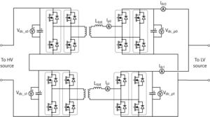
In TN151, an input series output parallel DAB application is shown, where the DABs are also controlled with phase-shift modulation.
A similar approach is used in the Fast EV charger with intermediate energy storage (AN007), where phase-shift modulation is used to control the secondary bus voltages of a Triple Active Bridge converter. In particular, experimental results show how the battery-side bus voltage is controlled after a step-change in the battery charging current.
Furthermore, the galvanic isolation provided by the transformer can also be used in grid-related applications, such as solid-state transformers (AN015).
Appendix
For those wanting to use a more advanced modulation technique, the illustrations below give a sneak peek of what can be easily done with ACG SDK on Simulink. As always, the exact same implementation is also possible with PLECS and with CPP SDK.


