Table of Contents
This application note details a possible control implementation on the B-Box RCP for a fast electric vehicle charger with intermediate storage.
In this example, the charger relies on a Dual-Active Bridge (DAB) stage to enforce galvanic isolation between the car and the grid. The DAB stage further comprises a third port, connected to a battery, making it a de-facto triple-active bridge.
Overall, the three ports are hence connected to:
- the 3-phase grid, using an NPC-type rectifier ;
- the intermediate battery through a 4-legs interleaved DC/DC converter ;
- the car battery (load) also through a DC/DC converter.
Simulation and experimental results using Simulink / PLECS and the imperix ACG SDK are shown.
System description
The overall system structure of the fast electric vehicle charger is shown below. The three ports of the medium-frequency transformer are shown on the same “side” of the magnetic circuit for convenience of representation.
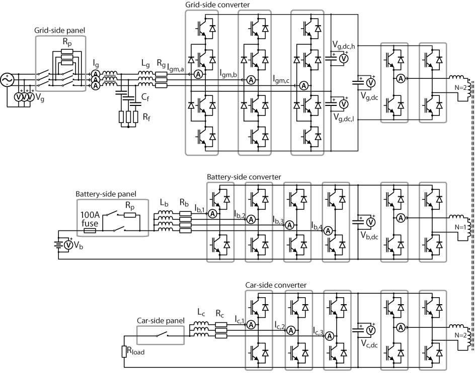
This system can be implemented using various imperix products, plus the necessary transformer and additional inductors.
Operating principles of the fast electric vehicle charger
System start-up and grid connection
As with any Voltage Source Converter (VSC) topology, this system requires that the DC bus is appropriately pre-charged before normal operation can be initiated. To this end, a pre-charge circuit is introduced between the converter and the grid, made of a three-phase set of resistors. These resistors can be later bypassed during normal operation, thanks to a software-controlled relay. TN131 gives further recommendations regarding system start-up techniques for grid-tied applications.
Grid-side control
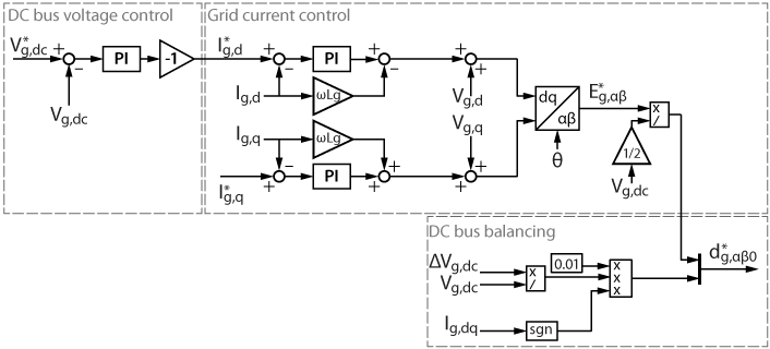
The control of the inverter is subdivided into 2 parts. First, a closed-loop controller regulates the bus voltage by drawing current from the grid. Second, this grid current is controlled in the stationary reference frame. A conventional dq-type PLL is used for the grid synchronization.
The relevant documentation is given below:
- Vector current control (TN106) details the design current controller.
- Cascaded voltage control (TN108) details the design of the bus voltage controller.
- DC bus balancing for NPC converters (TN129) details the design of the DC bus balancing.
- Three-phase NPC inverter (TN135) details the topology and the control of an NPC inverter, with an example of a grid-tied NPC inverter.
Control of the Triple Active Bridge (TAB)
The isolated DC/DC converter system is a shared stage that controls the power flows among all three ports of the system. More specifically, the TAB controls the voltages of the secondary DC busses by routing the appropriate amount of power towards those ports.
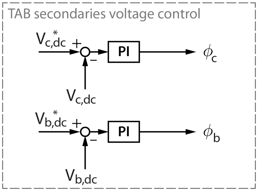
The TAB control uses phase-shift modulation, as presented in Operation of DAB converters (TN116) and adapted to a 3-port system. Phase-shift modulation allows a high power transfer through the TAB and acts only on \(\phi_c\) and \(\phi_b\), the phase-shifts between the grid-side switched voltage and each of the secondaries switched voltages, as shown below.
The main difference with the DAB presented in TN116 is that the power flows in a three-port system are interdependent. However, when the power transfer is mainly between two ports (i.e. the power consumed by one of the secondaries is close to zero), a decoupled control of the secondary DC buses is less challenging.
The DC bus voltage control of the car-side and battery-side is simply implemented as follows:
Control of the battery charger
The battery is connected to the TAB through a 4-legs interleaved DC/DC converter. The output of each leg is connected to the battery through an inductor, and there is one current PI controller for each leg of the converter.
The carriers of the legs N°1 and 3 have a phase set to 0, and the legs N° 2 and 4 have a phase set to 0.5 (180°): this technic allows to reduce the total battery current ripples.
The relevant documentation is given below:
- Basic PI control implementation (TN105) details the implementation of a basic PI current controller.
- Interleaved buck converter (TN122) details the topology and control of a DC/DC converter, with a 4-legs interleaved DC/DC converter as an example.
Car-side control
The car (more specifically its battery) is connected to the TAB through a 3-legs DC/DC converter. As for the intermediate battery, the output of each leg is connected to the battery through an inductor, and there is one current PI controller for each leg of the converter. The car battery is modelized as a 10 Ω resistor.
The carriers are not phase-shifted for this converter. The relevant documentation is the same as the intermediate battery control.
Action variables
The overall control for this fast electric vehicle charger has 3 action variables, which correspond to the 3 degrees of freedom:
- The grid reactive current reference Iq_ref. While the active current is controlled by the DC bus voltage regulator, the reactive current can be set freely by the user.
- The intermediate battery charge/discharge current reference. As seen above, the battery current is symmetrically distributed between the 4 legs of the DC/DC converter.
- The car battery charge/discharge current reference.
Physical realization of the fast electric vehicle charger
Software resources
The above-provided zip archive contains:
Charger_for_EV.slx: Main Simulink file. A PLECS viewer-enabled variant is also available.parameters.m: Initialization file (system parameters and calculation of the closed-loop controllers’ parameters).desired_states.mandstates.m: Matlab files containing the enumerations used for the state machines.frontpanel0.bbox: The file containing the analog input configuration for B-Box RCP. There are three files: one for each B-Box (one master and two slaves).RemoteControl_GUI folder: This contains the graphical user interface itselfRemoteControl_GUI.mlappas well as a required Java-enabled UDP communication scriptjudp.mandsystem_scheme.png.
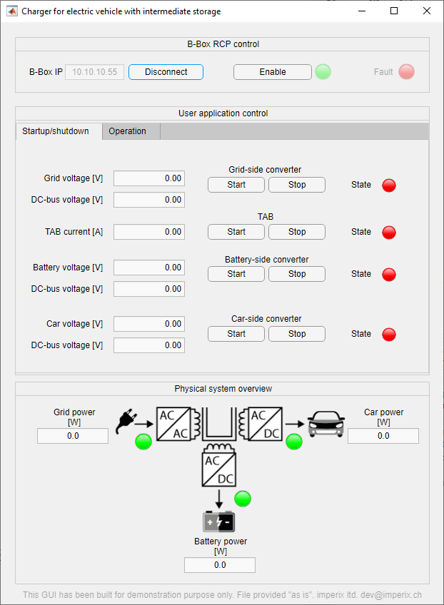
A graphical user interface (GUI) was developed to control the fast electric vehicle charger without Cockpit software. This GUI, created using the AppDesigner tool from Mathworks, uses Ethernet communication to exchange data with the B-Box RCP. The figure below shows a view of the interface. More information on setting up such an interface is available in PN130.
Required hardware and wiring
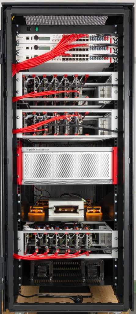
Experimentation on this Application Note can be made using standard and custom imperix equipment:
Standard:
- 3x B-Box RCP
- 2x SFP cables
- 1x Open rack with 3x PEN8018 and 2x PEB8032 modules (Grid side)
- 1x Open rack with 5x PEB8032 modules (Car side)
- 1x Open rack with 6x PEB4046 modules (Intermediate battery side)
- 1x Passive filters racks or:
- 3x 2.5mH inductor 22A (Lg)
- 3x 3µF capacitor (Cgf)
- 3x 1Ω resistor (Rgf)
- 4x DIN800V voltage sensors
- 3x DIN50A current sensors
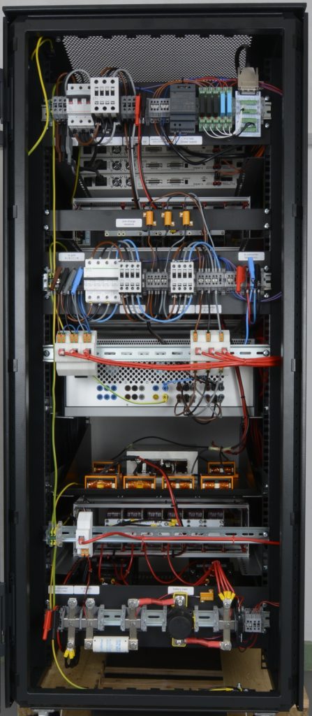
- 1x Grid connection panel with:
- 1x circuit breaker (3ph 16A)
- 2x controllable relay (3ph 16)
- 3x 47Ω precharge resistors
Custom:
- 1x Passive shelf with:
- 1x 3 ports MF transformer
- 3x leakage inductors
- 1x Passive shelf with:
- 4x 2.5mH inductor 30A (Lb)
- 1x Battery connection panel with:
- 1x controllable DC relay 100A
- 1x fuse 100A
- 1x 47Ω precharge resistor
- 1x controllable DC relay 5A
- 1x Car connection panel with:
- 1x circuit breaker 32A
- 1x controllable relay 32A
In addition, the following equipment is needed:
- 3x load inductors (LL)
- 3x load resistors (RL)
The following table summarizes the parameters used to test this application.
| Parameter | Value | Parameter | Value | Parameter | Value |
|---|---|---|---|---|---|
| Inductance Lg | 2.5mH | Inductance Lb | 2.5mH | Grid side DC bus voltage reference | 700 V |
| Resistance Rg | 22 mΩ | Resistance Rb | 13 mΩ | Car side DC bus voltage reference | 700 V |
| Capacitance Cgf | 3 µF | Inductance Lc | 2.5mH | Battery side DC bus voltage reference | 350 V |
| Resistance Rgf | 1 Ω | Resistance Rc | 22 mΩ | Grid voltage (ph-N, RMS) | 230 V |
| PWM frequency (grid, TAB, and car sides) | 20 kHz | PWM frequency (battery side) | 10 kHz |
Simulink implementation
Within the provided Simulink file, the Input mode selector variable allows selecting how the setpoints and other references are transferred to the control code:
- Mode=0. The control code uses Simulink step blocks. This is useful during off-line simulation.
- Mode=1. The code uses the tunable variables. This is useful for tuning parameters live with Cockpit.
- Mode=2. The control code uses inputs from the Ethernet blocks. This is useful when using the GUI.
System start-up
These steps can be followed to start the system:
- Prior to generating run-time code, configure the input mode selector to either receive setpoints from the ETH blocks, or from tunable variables that can be freely changed later using Cockpit.
- Generate run-time code for the provided Simulink file using imperix’s SDK for automated code generation. Consult the Quick-start guide if needed.
- Connect to the B-Box RCP using Cockpit. Consult this Quick-start guide if needed.
- In Cockpit, add a Variables module and drag and drop the following variables:
State_g_desired, State_t_desired, State_b_desired, State_c_desired Ig_q_ref, Ib_ref and Ic_ref, and the probe variables:
State_g, State_t, State_b, Stated_c, Vg_dc, Vb_dc, Vc_dc, Vb, Ig_d, Ig_q, Ic, Ib, - Check that all analog inputs are correctly configured and protection thresholds appropriately adjusted. Consult PN105 for detailed instructions if needed.
- Check that the variables State_g_desired, State_t_desired, State_b_desired,State_c_desired, Ig_q_ref, Ib_ref and Ic_ref are set to 0, and click on Enable the PWM outputs to enable the generation of PWM signals.
- Activate the pre-charge and the regulation of the grid side DC bus by setting State_g_desired to 1.
- When the DC bus voltage is stabilized (i.e. when State_g is “READY”), activate the TAB magnetization and regulation by setting State_t_desired to 1. Check that the voltages Vg_dc, Vb_dc, and Vc_dc are constant.
- When the TAB is ready (i.e. when State_t is “READY”), activate the intermediate battery relay and regulation by setting State_b_desired and State_c_desired to 1.
- Check that State_b and State_c are “READY”, and that the currents Ib and Ic are null.
- Set the desired current references Ib_ref, Ic_ref, and Ig_q_ref.
System shut down
The following steps detail the procedure to shut the system down:
- Set the current references Ib_ref, Ic_ref and Ig_q_ref to 0.
- Deactivate and disconnect the intermediate battery and the car by setting State_b_desired and State_c_desired to 0.
- Check that the disconnection has been made (i.e. when State_c and State_b are “STANDBY”).
- Deactivate the TAB by setting State_t_desired to 0. The DC bus voltages Vb_dc and Vc_dc will start to discharge.
- Deactivate and disconnect the grid by setting State_g_desired to 0. The grid DC bus will also start to discharge.
- To dissipate the DC bus energy, the voltage references Vb_dc_ref and Vc_dc_ref can be set to 0, and then activate the TAB by setting State_t_desired to 1: the DC bus voltages decrease quickly until zero, by switching losses.
- Block all PWM output signals by clicking on Disable the PWM outputs.
Remote control GUI
To allow the exchange of data between the computer and the B-Box RCP, the necessary steps are as follows:
- Specify the computer address in the ETH blocks of the Simulink file. The B-Box RCP will transmit its measurements and status information to this address.
- Generate run-time code and connect to the B-Box RCP using Cockpit. Consult this Quick-start guide if needed.
- Make sure that the Windows firewall doesn’t block communication with the B-Box.
- Open the app and specify the IP address of the B-Box. Click on the connect button.
More information on the use and modification of the GUI is given in GUI with the App Designer (PN130).
Experimental results from the fast electric vehicle charger
1) Grid-side precharge
First, the precharge relay is activated. The DC bus voltage rises to approximately 565V (which is the grid line peak voltage). Finally, the PWMs of the NPC inverter are activated, and the closed-loop control regulates the DC bus voltage to 600V.
2) TAB magnetization and regulation
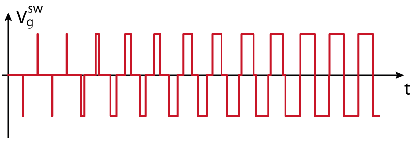
Once the grid-side DC bus is charged and regulated, the transformer of the TAB can be magnetized and the secondary DC buses can be precharged. To do so, a switched 3-level voltage with a gradually increasing duty-cycle is applied to the TAB primary, as shown below. This imposes a gradually increasing current in the transformer, charging the secondaries. To ensure that the transformer current stays centered around zero, the duty-cycle of the generated pulses is increased only every two switching periods to maintain symmetry between the positive and the negative pulses.
The figure below shows the DC bus voltages, the relative phase of secondaries of the TAB, and the activation of the PWMs of the secondaries:
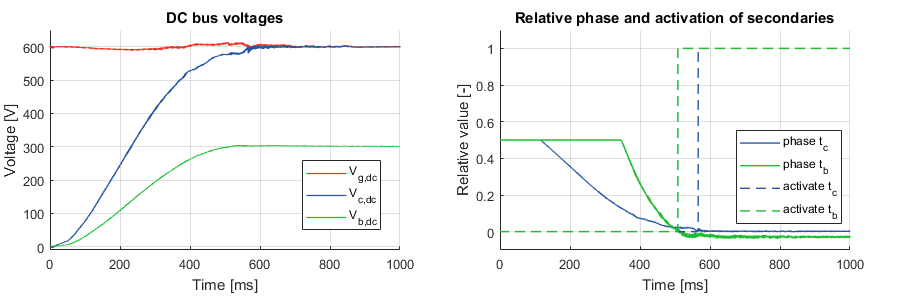
The magnetization of the transformer required a certain amount of energy which is provided by the grid-side DC bus voltage. By consequence, the grid-side DC bus voltage decreases a little before being regulated back to 600V by the controller.
For each one of the secondaries of the TAB, the PWMs are enabled when the voltage reaches the required value.
3) Control of the battery charger
Once the two secondaries are charged and regulated, the intermediate battery can be charged. The next graph shows a reference step on the battery current and the response of the whole system:
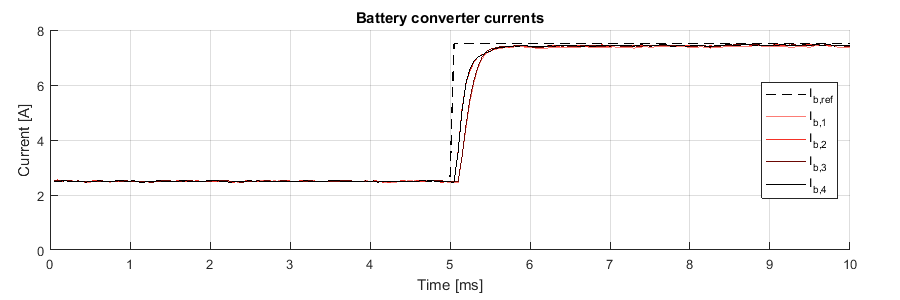
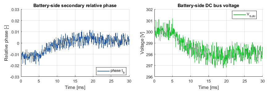
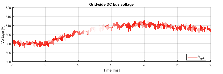
The 4 legs of the DC/DC converter can easily follow the current reference. We can see the difference in response between the 2 phases with a 0% phase shift and the 2 phases with a 50% phase shift, due to different control delays, as further detailed in Interleaved DC-DC converter control.
Due to the jump of current (consequently power) reference, the battery-side DC bus starts to decrease, but the controller regulates it by increasing the relative phase of the secondary.
The grid-side DC bus voltage should also decrease due to the power reference step. However, this voltage rises due to the feedforward of the battery current reference to the grid-side current controller. By consequence, the grid-side current control starts to take some power from the grid (and then the grid-side DC bus voltage increases) before the TAB controller regulates the secondary DC bus voltage.
4) Car charging
Now that the intermediate battery has been charged through the grid, the final step can be performed: both the grid and the intermediate battery power flows are combined to charge the car battery.
The next graph shows a reference step on the car current and the response of the system:
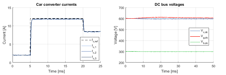
The power flow from the intermediate battery stays constant because the intermediate battery current reference is set by the user. Consequently, the intermediate battery DC bus voltage is almost not destabilized by the reference step on the car current.
The power flow step of the car battery is compensated by the grid. As for the previous experimental results, the grid-side DC bus voltage increases slightly because the car battery current is feedforwarded to the grid current controller.
The correct behavior of the fast electric vehicle charger has been validated.


