Table of Contents
This technical note presents various techniques for the DC bus balancing of NPC converters. These techniques are notably used in TN135, which implements a grid-tied NPC inverter. More generally, information about Neutral Point Clamped (NPC) converters is given in TN132.
In multilevel converters, and therefore in NPC converters, a possible imbalance between the internal DC half-busses may overstress – or even damage – the capacitors and semiconductors. Besides the risk of damage, the output voltages and phase currents may also be affected. As such, maintaining adequate balance is necessary at all times.
To this aim, two methods are proposed here. The first one can be used with a carrier-based modulation (CB-PWM), while the second one is designed for space-vector modulation (SV-PWM). After a brief description of each scheme, the Simulink models are provided and experimental results are shown.
Cause of the voltage imbalance
Generally, the overall voltage of the DC link is controlled by a cascaded control. However, the voltage of each half-bus is not controlled individually. This is why an imbalance may occur, even if the total DC bus voltage remains constant.
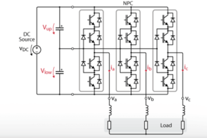
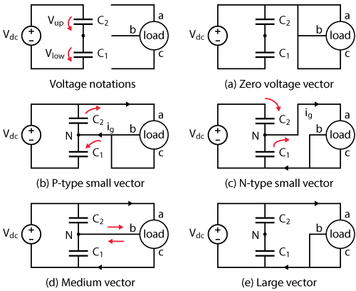
During the converter operation, each phase can have three possible states:
- “P”, when the phase is clamped to \(V_{dc}/2\),
- “O”, when the phase is clamped to the midpoint of the DC bus,
- “N”, when the phase is clamped to \(-V_{dc/2}\).
Consequently, a three-phase NPC converter has 27 possible states, which can be represented as vectors in the Clarke referential, as presented in TN132:
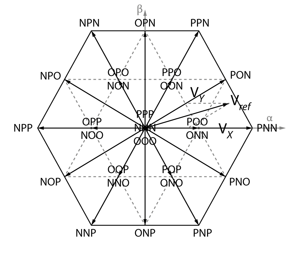
These vectors can be divided into four groups according to their magnitude: zero vectors (0), small vectors (\(V_{dc}/3\)), medium vectors (\(V_{dc}/\sqrt{3}\)) and large vectors (\(2V_{dc}/3\)).
The effect of each one of these vector groups on the balancing of the NPC converter is represented in Fig. 2. The corresponding current path determines the sign of the corresponding imbalance.Zero and large vectors don’t have any balancing or unbalancing effect. Medium vectors do have some impact depending on the load conditions. Small vectors have the largest impact [1].
Balancing methods for NPC converters
In this technical note, two different methods are presented to balance the DC bus voltage of an NPC converter: one for carrier-based modulation (CB-PWM) and the second for space-vector modulation (SV-PWM).
Carrier-based PWM
With CB-PWM, each of the two carriers is related to its corresponding half DC bus voltage. Therefore, if the amplitude of the carriers is changed to reflect the effective voltage, the utilization of the DC link is changed [2]. This is shown in the picture below:
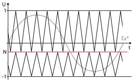
In practice, it is often easier to achieve the balancing of NPC converters by altering the value of the duty cycle rather than the amplitude of the triangular carrier. Therefore, the same result can be observed using the following formula:
$$\begin{align} d_1′ &= \displaystyle\frac{d_1 + x}{1+x} & d_2′ &= \displaystyle\frac{d_2}{1-x} \end{align}$$
where the correction factor \(x\) is proportional to the normalized DC unbalancing and defined as:
$$x = \displaystyle\frac{V_{dc,up}-V_{dc,low}}{V_{dc}} \cdot \text{sgn}(I_d)$$
When the converter is sourcing power to the load (\(I_d \geq 0\)) and \(V_{dc,up} > V_{dc,low}\), the correction leads to \(d_1′ > d_1\) and \(d_2′ > d_2\) to encourage the « P » state on each leg: according to Fig. 2, C2 is discharged. Reciprocally, when the converter is sinking power from the load, \(d_1′ < d_1\) and \(d_2′ < d_2\) to encourage the « O » state and charge C2. The same reasoning can be applied with \(V_{dc,up} < V_{dc,low}\).
Space vector PWM
With SV-PWM, a possible bus balancing procedure is based on the redundancy between small vectors: although leading to the same line-to-line voltages, they correspond to different configurations where the current is charging C1 and discharging C2 (P-type) or discharging C1 and charging C2 (N-type).
After having located the desired voltage Vref in the αβ-plane and identified the three closest vectors Vx, Vy, and Vz, the corresponding duty cycles dx, dy, and dz are computed so that the average applied voltage is equal to Vref. In the example of Fig. 1, Vx=PNN, Vy=PON, and Vz=POO/ONN. The duty cycle dz can hence be decomposed into dzP and dzN for the application of POO and ONN respectively, with dz=dzP+dzN.
Usually, to reduce the number of commutations, these vectors are applied in a given pattern, as shown in Fig. 4, where da, db, and dc are the applied duty cycles. It appears that changing the duty cycle dzN (and dzP) is equivalent to shift da, db, and dc.
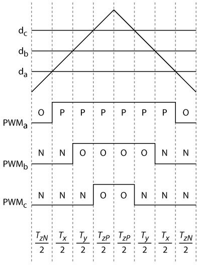
in SV-PWM
Subsequently, the duty ratios are computed as:
$$\begin{aligned} d_a&=d_x+d_y+d_{zP} & d_b&=d_y+d_{zP} & d_c&=d_{zP}\end{aligned}$$
with \(d_{zP} = d_z/2 +x\) and \(x = \displaystyle\frac{V_{dc,up}-V_{dc,low}}{V_{dc}} \cdot \text{sgn}(I_d)\).
Adding the same correction \(x\) to the duty cycles of each phase is equivalent to adding a homopolar component to the reference vector \(E_{\alpha\beta 0}^*\).
Simulink models
The proposed balancing schemes, also shown in Fig. 5 and 6, can be downloaded as Simulink models. The proposed methods have been simulated and experimentally validated in TN135.


Experimental results
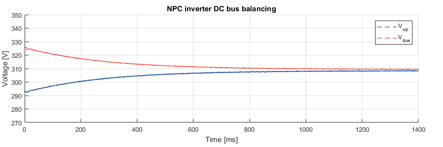
To illustrate the operation of the proposed techniques, the balancing was tested with a simple grid-connected operation. To this end, the DC bus was initially charged with unbalanced conditions(\(\Delta V \approx 30\,\text{V}\)) before the converter starts switching.
The following graph shows the experimental result with the method for SV-PWM. Proper balancing (i.e. normalized unbalance < 1%) of the NPC converter is achieved after approximately 1s.
References
[1] K. H. Bhalodi, P. Agrawal, “Space Vector Modulation with DC-Link Voltage Balancing Control for Three-Level Inverters”, in IEEE PEDES Conference, New Delhi, 2006.
[2] W. Kołomyjski, “Modulation Strategies for Three-level PWM Converter-fed Induction Machine Drives”, PhD Thesis, Warsaw University of Technology, 2009.