Table of Contents
What is the space vector modulation technique (SVM) and how does it work? To answer these questions, this article introduces first the notions of active and zero space vectors and their representation in the Clarke referential. It presents then how to use space vectors to synthesize any output voltage with two or three-level inverters.
A demonstration code example is provided and freely available. It can be tested in simulation using imperix ACG SDK and validated in the laboratory with a B-Box RCP programmable controller and PEB half-bridge power modules.
Space vector modulation for two-level inverters
Active and zero space vectors
Space vector modulation is an alternative to the Carrier-Based modulation technique that is used in the Three-phase Voltage Source Inverter (VSI) application note. Both methods are similar, in the sense that they transform a reference voltage into switching signals for the inverter. However, SVM operates in the Clarke referential (αβ) rather than the abc one [1]. The topology of a two-level three-phase inverter is presented in the figure below.
In the αβ frame, each switching state of the inverter is represented by a space vector. Then, since the DC bus should not be short-circuited, the upper and lower switches of each leg must operate in a complementary way. As such, there are only eight possible switching states for the inverter. In this note, the state of a leg is “1” if the upper switch is conducting, and “0” if the lower switch is conducting.
The eight possible space vectors are summarized in the table below: V0 and V7 are called zero space vectors as they do not produce any phase voltage. By contrast, V1 to V6 produce non-zero phase voltages and are called active space vectors.
| Space vector | State leg A | State leg B | State leg C | va | vb | vc |
| V0 | 0 | 0 | 0 | 0 | 0 | 0 |
| V1 | 1 | 0 | 0 | 2 VDC/3 | -VDC/3 | -VDC/3 |
| V2 | 1 | 1 | 0 | VDC/3 | VDC/3 | -2 VDC/3 |
| V3 | 0 | 1 | 0 | VDC/3 | 2 VDC/3 | – VDC/3 |
| V4 | 0 | 1 | 1 | -2 VDC/3 | VDC/3 | VDC/3 |
| V5 | 0 | 0 | 1 | -VDC/3 | -VDC/3 | 2 VDC/3 |
| V6 | 1 | 0 | 1 | VDC/3 | -2 VDC/3 | VDC/3 |
| V7 | 1 | 1 | 1 | 0 | 0 | 0 |
Voltage synthesis with space vector modulation
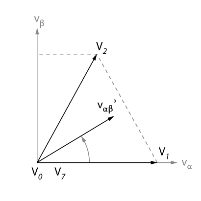
The space vector modulation method has only eight space vectors at its disposal. However, other space vectors can be synthesized – on average – by alternating several active and zero vectors over a switching period \(T_{sw}\) of the modulator. For example, the active vectors V1 and V2 can be used to synthesize a reference space vector \(V_{\alpha\beta}^*\) with an angle between 0 and 60° – see the figure below – while the zero vectors V0 and V7 allow reducing the amplitude of this reference vector. The amplitude of the average space vector is then expressed as
$$\vec{V}_{\alpha\beta}^* = \frac{T_1\vec{V}_1 + T_2\vec{V}_2 + T_0\vec{V}_0 + T_7\vec{V}_7}{T_{sw}},$$
with \(T_1\), \(T_2\), \(T_0\), and \(T_7\), the application times of each vector. In the literature, the application times are also referred to as dwell times [1].
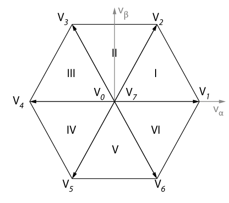
When synthesizing a space vector with SVM, the feasible space in the αβ plane is a hexagon, as shown in the figure below. Then, the active space vectors divide the hexagon into six triangular sectors. In the first sector, the active vectors V1 and V2 are used.
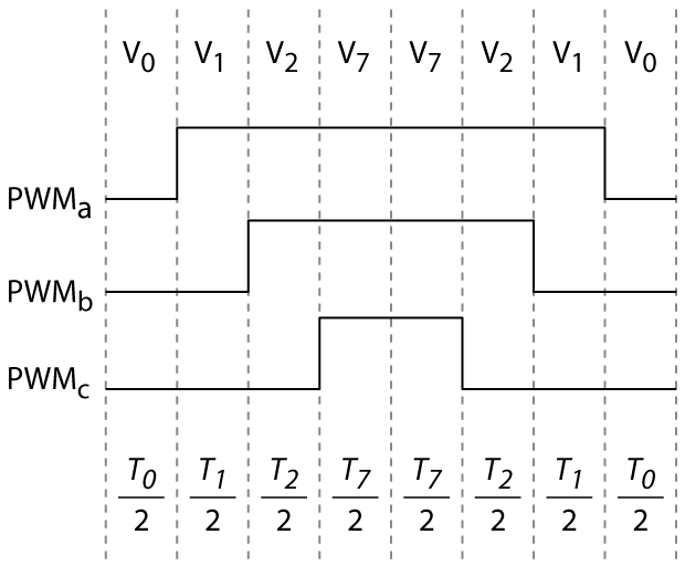
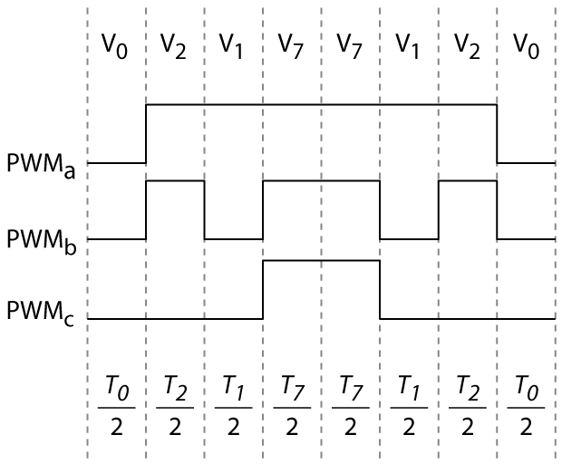
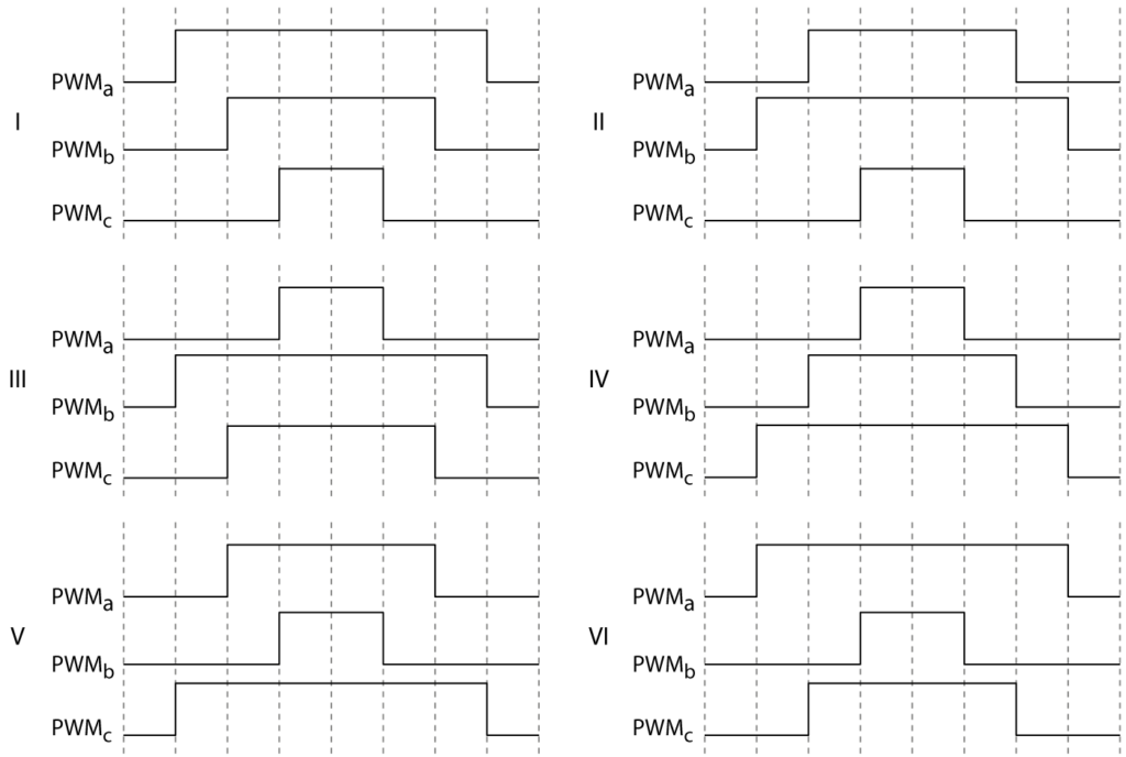
The SV-PWM modulator from imperix libraries will automatically select the appropriate active vectors and choose the dwell times, based on the angle and the amplitude of the input reference space vector. The switching sequence is then made symmetrical in order to minimize switching losses. The figures below illustrate how the same active and zero space vectors can produce different switching patterns (or PWM signals) for sector I, which are either optimal or sub-optimal in terms of switching losses.
For reference, the optimal switching patterns for each sector are presented in the next figure.
Space vector modulation for three-level inverters
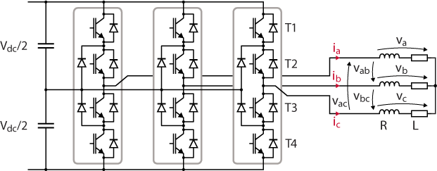
The space vector modulation technique for two-level inverters can be generalized to three levels [2]. A three-level converter has three possible switching states per leg, denoted P (positive output voltage), N (negative output), and 0 (zero output). In total, the converter has 27 possible switching states. NPC inverters are a typical example of three-level converters (see the topology below).
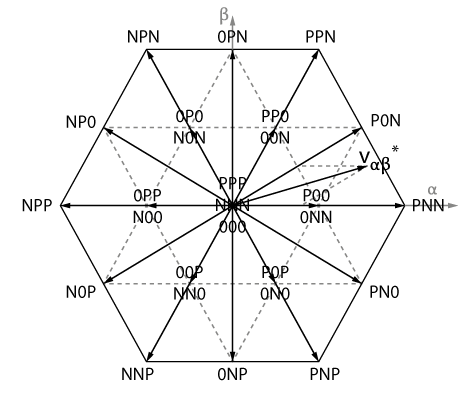
As for the two-level inverter, each switching state is represented by a space vector in the Clarke referential. Similarly, the feasible space in the Clarke referential is also a hexagon, as shown below. In terms of voltage synthesis, a three-level converter has more degrees of freedom, since it has more space vectors at disposal. Nevertheless, the same basic concept as before applies: look for the closest active and zero vectors, and alternate between them to produce the reference space vector on average.
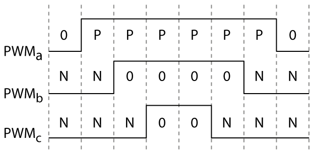
In order to find appropriate active and zero vectors to apply, the SV-PWM modulator from imperix libraries uses a hexagonal coordinate system, as presented in [2], rather than a division in six sectors. While the search method differs from the two-level variant of the algorithm, switching patterns are constructed with the same logic: commutations are avoided as much as possible to limit switching losses. The figure below illustrates an example of an optimal switching pattern generated by a three-level converter.
Experimental validation of space vector modulation
Implementation using MATLAB Simulink
The attached Simulink model provides an example of a current controller similar to the one presented in the vector current control note. However, a space vector modulation technique is used instead of a carrier-based one. The power converter is a two-level three-phase inverter.
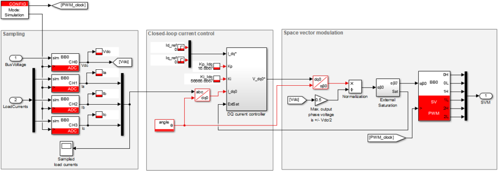
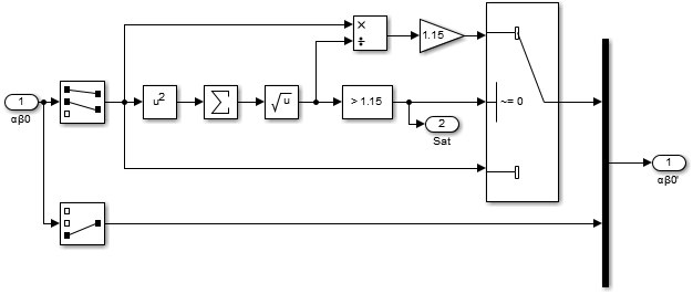
As explained in SVPWM vs SPWM modulation techniques, the maximum amplitude of the reference space vector is limited by the DC bus voltage. When normalized with respect to the DC bus, the maximum output voltage can only reach \(2/\sqrt{3} \approx 1.15\) p.u. before entering the overmodulation region. If this threshold is exceeded, the load currents would be distorted, which is undesired for current control. For this reason, the control should saturate the output voltage.
Let us call \(m_{\alpha}\) and \(m_{\beta}\) the components of the reference space vector. If the norm is larger than 1.15, it exceeds the limit by a ratio
$$ R = \frac{\sqrt{m_\alpha ^2 + m_\beta ^2}}{1.15}.$$
In this case, the \(\alpha\) and \(\beta\) components should be reduced by a factor \(R\) to avoid entering the overmodulation region, as shown below. While saturating, the current controller cannot follow its d and q references, since it cannot produce the required output voltage [3]. As such, the integrator of each PI regulator should be disabled, to prevent accumulating the error. The SV-PWM modulator from imperix libraries has a built-in saturation mechanism. However, by implementing the saturation externally – as shown below – one has access to a boolean signal that notifies the current controller if it operates in the saturation region. As such, the controller can conditionally disable its integrator.
Experimental setup
During the experiments, the two-level converter was connected to a balanced three-phase RL load, under the following conditions:
- DC bus voltage: 100 V
- Control frequency and sampling: 20 kHz
- Sampling phase: 0.5
- Load resistance: 8.5 Ω
- Load inductance: 2.5 mH
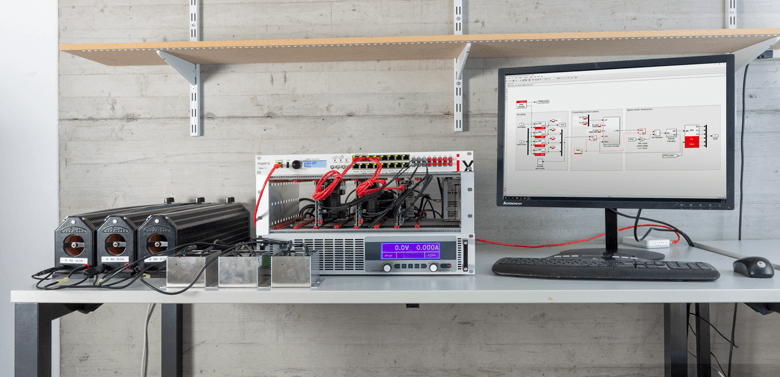
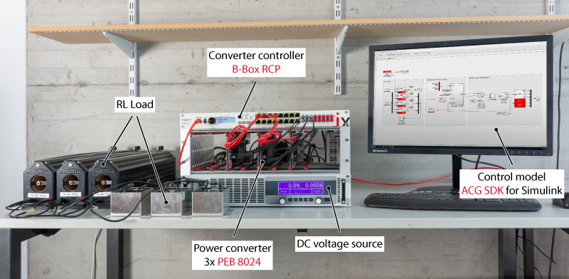
The experimental setup is presented in the picture below. The power converter is built from 3x PEB 8024 phase-leg modules and is controlled by a B-Box RCP prototyping controller. The current control is implemented graphically using the ACG SDK library for Simulink.
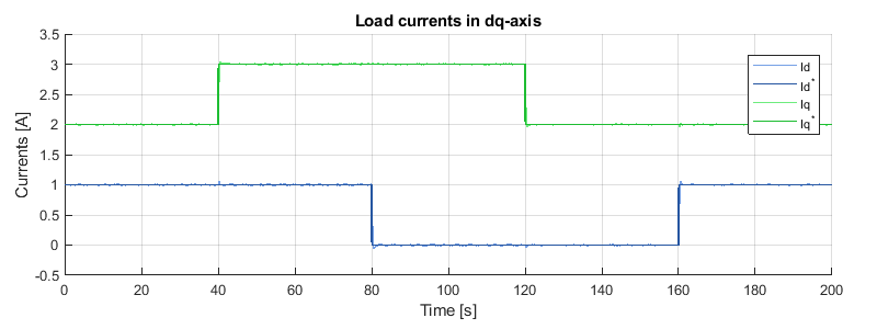
The performances of the current controller were validated experimentally by applying multiple steps on the d and q-axis current references. As illustrated below, the controllers of both axes manage to independently track their respective references, while rejecting perturbations.
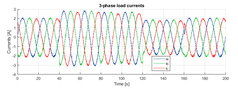
For the sake of completeness, the experimental measurements of the three-phase load currents are also illustrated below.
Academic references
[1] Slobodan N. Vukosavic, “Grid-Side Converters Control and Design”, Springer, 2018, ISBN: 978-3-030-10346-0
[2] N. Celanovic and D. Boroyevich, “A fast space-vector modulation algorithm for multilevel three-phase converters,” in IEEE Transactions on Industry Applications, vol. 37, no. 2, pp. 637-641, March-April 2001, doi: 10.1109/28.913731.
[3] Karl J. Åström and Tore Hägglund, “PID Controllers: Theory, Design and Tuning”, Instrument Society of America, 1995, ISBN:1-55617-516-7


