Table of Contents
The sin/cos encoder (S/C) block retrieves the Sine and Cosine signals of a sin/cos encoder connected to the Motor Interface.
The B-Box RCP supports up to two sin/cos encoders through the Motor Interface for B-Box RCP. This type of sensor encodes the position of the rotor using two signals in quadrature (sin and cos). The principle is similar to an incremental encoder: the signals in quadrature are periodic, and the sensor produces a fixed number of periods per revolution (PPR). Unlike an incremental encoder, signals in quadrature are analog, which allows computing the angle within one electrical period of the sensor. As a result, a sin/cos encoder offers a better resolution at the same PPR. Additionally, some sin/cos encoders also provide an index signal (ns) equivalent to the Z reset signal of an incremental encoder. The Motor Interface does not support absolute sin/cos encoders.
Version 3.7 beta of the ACG SDK for Simulink does not implement an angle decoder. Instead, the S/C block provides the raw analog signals of the sensor read by some ADCs, and the control must implement angle decoding.
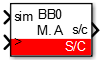
Simulink block
Signal specification
- The output
s/cis a vector containing the Sine and Cosine signals in [V]. - The optional output
nscorresponds to the index signal. - The
siminput is used in simulation and represents the actual Sine and Cosine signals, computed by the simulation plant model. - The
>input signal needs to be connected to the sampling clock generated by the CONFIG block to account for the exact sampling instant in simulation.
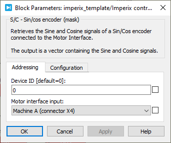
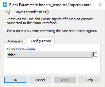
Parameters
Device IDselects which B-Box/B-Board to address when used in a multi-device configuration.Motor Interface inputselects which connector of the Motor Interface is used as an input.Output index signaldefines if the index signal is output or not.
PLECS block
Signal specification
- The output
s/cis a vector containing the Sine and Cosine signals in [V]. - The optional output
nscorresponds to the index signal. - The
siminput is used in simulation and represents the actual Sine and Cosine signals, computed by the simulation plant model. - The
>input signal needs to be connected to the sampling clock generated by the CONFIG block to account for the exact sampling instant in simulation.

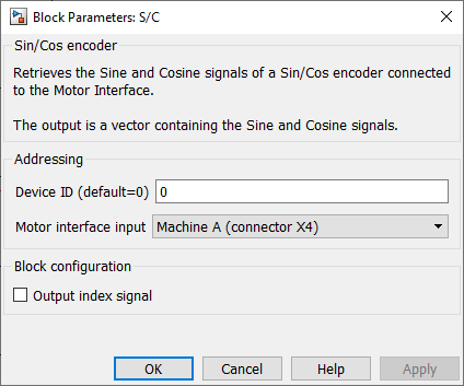
Parameters
Device IDselects which B-Box/B-Board to address when used in a multi-device configuration.Motor Interface inputselects which connector of the Motor Interface is used as an input.Output index signaldefines if the index signal is output or not.