Table of Contents
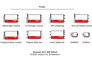
The VSR block is a simulation model included in the Imperix Power library. It implements the model of the imperix voltage sensor VSR-1000-ISO, VSR-500-HBW, and DIN800 V in Simulink and PLECS simulation.
For more information regarding the Imperix Power library, please read Getting started with Imperix Power library.
• ACG SDK 2024.2: First release. Support for PLECS and Simulink SPS library (“Black” blocks).
• ACG SDK 2025.2: Addition of thermal models for most PEB and PEN modules.
• ACG SDK 2026.1: Support for the latest products (PEB-800-40, VSR-1000-ISO, VSR-500-HBW, CSR-25-HBW).
• ACG SDK 2026.1.3: Support for Simulink Simscape Electrical library (“Blue” blocks).
• Simulink (R2016a or newer): Simscape is required.
• Plexim PLECS (4.5 or newer): No particular requirement.
Additionally, for Simulink:
• Simscape Electrical library: Simscape Electrical is required.
• SPS library: Simscape Specialized Power Systems (up to R2025b) or OPAL-RT SPS Software is required.
Modeling of VSR
The VSR model has two modeling levels:
- (A) Simple
- (B) Detailed
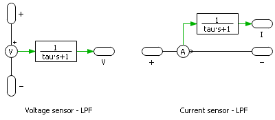
A generic sensor can be approximately modeled by an ideal sensor in series with an optional first-order Low-Pass Filter (LPF). The relationship between sensor’s bandwidth \(f_{BW}\) and the time constant \(\tau\) of the LPF follows \(\tau = \frac{1}{2\pi f_{BW}}\).
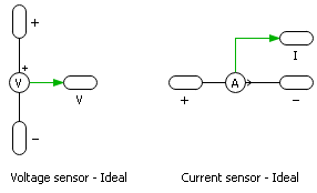
A sensor is modeled as a first-order LPF only if its bandwidth lies within the frequency range of a given modeling level. Otherwise, it is modeled as an ideal sensor. The following table summarizes the information on all the voltage sensors in the Imperix Power library.
| Sensor | Bandwidth [kHz] | (A) Simple | (B) Detailed |
|---|---|---|---|
| VSR-1000-ISO | 100 / 10 | Ideal | LPF |
| VSR-500-HBW | 3000 / 300 | Ideal | Ideal |
| DIN800V | 100 | Ideal | LPF |
Simulink VSR block
Port specification
- The output
Vis the measured voltage between the two electrical ports.


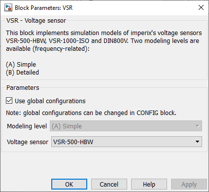
Parameters
Use global configurationsis ticked when the block receives global configurations from theConfigblock.Modeling levelselects the modeling level of the voltage sensor.Voltage sensorselects the type of the voltage sensor.
PLECS VSR block
Port specification
- The output
Vis the measured voltage between the two electrical ports.

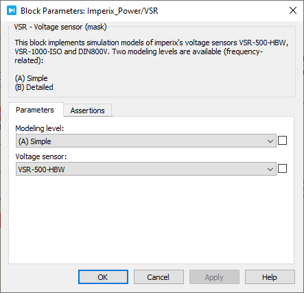
Parameters
Modeling levelselects the modeling level of the voltage sensor.Voltage sensorselects the type of the voltage sensor.
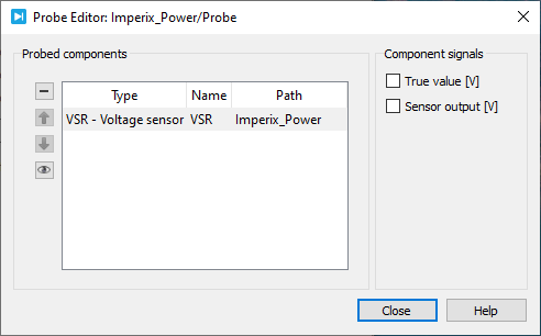
Probe signals
The following signals can be monitored by a Probe block in PLECS.
True value [V]monitors the true value of the measured voltage between the two electrical ports in Volt.Sensor output [V]monitors the physical output of the voltage sensor in Volt.