Table of Contents
This technical note presents a selection of the most prevalent grid synchronization methodologies employed in grid-tied power converters. These methods are crucial for enabling power converters to reliably inject high-quality power into the utility grid, even when subject to disturbed operating conditions.
The structure of this technical note is as follows: initially, the fundamental principles of grid synchronization are established. Then, an overview of the main categories of existing grid synchronization methods is provided. Following that, various approaches for implementing PLL-based techniques in single-phase inverters are presented and compared. Finally, PLL-based techniques for three-phase systems are introduced and experimentally evaluated under different disturbance conditions.
Some implementations of grid synchronization methods are available for download as Simulink and PLECS models on their respective pages (i.e., SOGI-PLL and SRF-PLL).
What is grid synchronization?
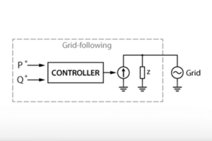
Grid synchronization is the imperative process by which power converters accurately estimate and conform their operation to the fundamental grid parameters: the phase angle, frequency, and voltage magnitude. This critical information is typically utilized to execute power flux calculations and/or coordinate transformations, which are indispensable for the independent control of the active and reactive power flows exchanged with the utility grid. These processes are notably essential for the operation of renewable energy sources, which are heavily dependent on power converters for their effective interaction with the grid.
From a broader perspective, grid synchronization is essential for maintaining the stability and reliability of the power system as a whole. Without proper synchronization, power quality issues can arise and may potentially result in damage to both the converter and the grid infrastructure.
Grid synchronization can be achieved through various control techniques. The foundational tool for achieving this is the phase-locked loop (PLL) [1]. The latter mainly consists of a feedback loop, designed to precisely track the frequency and phase of its input signal—specifically, the grid voltage. More advanced grid synchronization methods combine the PLL with filters applied to the input voltage, resulting in combinations that allow for the robust and precise estimation of the above-mentioned grid parameters even under unbalanced voltages, harmonic distortions, or voltage sags.
Classification of grid synchronization methods
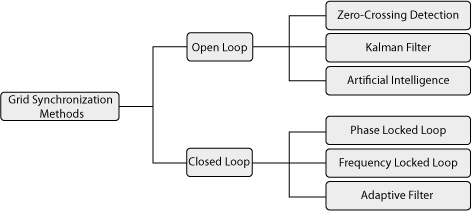
Numerous techniques exist for achieving grid synchronization, which can be broadly categorized into open-loop and closed-loop approaches as depicted below [2, 3].
Open-loop vs. closed-loop methods
Open-loop methods are based on detecting directly the grid voltage phase, frequency, and magnitude without using any feedback in their structure. As a result, they are simple to implement and generally require a low computational burden. Nevertheless, they are only suitable under ideal or slightly distorted grid conditions. Some of these techniques are zero-crossing detection, which is based on detecting the zero crossing of the grid voltage and therefore has slow dynamic performance; Kalman filter, which offers good accuracy but requires careful tuning of the covariance matrix and is computationally demanding; and artificial neural networks, which are accurate but need to be trained using real data, which is sometimes hard to obtain.
Closed-loop methods, on the other hand, have at least one feedback signal in their structure. This feedback loop aims to lock the estimated phase or frequency to the grid values, allowing the method to dynamically track changes in frequency or distortion. Due to this adaptive behavior, closed-loop systems generally offer greater accuracy, robustness to disturbances, and better overall synchronization performance. Therefore, in general, these methods are preferred for grid-connected systems. Some of the different methods are explained in the following section.
General overview of closed-loop methods
As shown in Fig. 1, closed-loop methods can be further divided into phase-locked loop (PLL) techniques, frequency locked loop (FLL) techniques, and adaptive filters.
PLL techniques are widely described in the literature [1]. They are based on a feedback control loop that tracks the phase of the input signal. They provide accurate and reliable phase and frequency synchronization, especially in three-phase systems with balanced signals. However, their single-phase implementation tends to be more challenging due to the absence of natural phase references. Moreover, PLLs are sensitive to disturbances such as noise, harmonics, and grid imbalances. To address these limitations, advanced strategies that include a filtering stage at the input have been developed.
FLL techniques, on the other hand, focus on frequency detection rather than phase angle tracking. They operate through a feedback loop that includes a frequency error detector and a controller, which continuously adjusts the estimated frequency to match the actual grid frequency. FLLs are particularly advantageous compared to PLLs in weak or distorted grids, as they offer improved tracking performance and a fast, stable response. Nevertheless, since they do not estimate the phase of the grid voltage, they are often used in conjunction with a PLL, which increases the overall system complexity and computational burden.
Adaptive filters serve to extract the fundamental frequency component from the measured grid voltage signal. They dynamically adjust their internal parameters in real time using adaptation algorithms within a feedback loop. This adaptability allows them to effectively track frequency variations and suppress harmonics or noise, making them well-suited for grids with highly variable conditions. Nevertheless, their implementation is typically more computationally intensive compared to PLL-based methods.
As a result, among these techniques, PLL-based methods remain the most commonly implemented solution for grid synchronization due to their balance between precision, robustness, and relatively simple implementation. Therefore, the rest of the note is focused on the PLL-based techniques.
PLL implementation in single-phase and three-phase systems
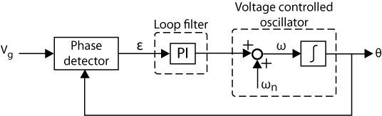
The structure of the PLL-based techniques is typically formed by a phase detector, a loop filter (commonly a PI controller), and a voltage-controlled oscillator (commonly an integrator with windup).
In three-phase systems, the implementation of these systems is relatively straightforward as the availability of three distinct phase signals enables a direct transformation to the synchronous reference frame (dq frame), facilitating accurate phase tracking.
In contrast, implementing PLL-based systems in single-phase systems presents a greater challenge. Indeed, the lack of multiple-phase signals prevents a direct application of the dq transformation, which is essential for conventional PLL operation. As a result, various techniques have been proposed to reconstruct a pseudo-orthogonal signal (typically the β-axis) from the single-phase input (α-axis), enabling the application of similar PLL strategies as the ones used in three-phase systems.
In the next sections, various PLL-based methods for both single-phase and three-phase systems are detailed.
PLL-based methods for single-phase systems
Due to the above-mentioned challenge of reconstructing a pseudo-orthogonal signal, different categories of single-phase PLLs can be described, based on how the quadrature signal is generated [4]:
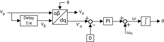
a) T/4 transport delay-PLL
This technique is based on generating the quadrature signal by delaying the measured voltage by 90º of the fundamental period (T/4). This technique is easy to implement, but is only effective at the nominal frequency. If the grid frequency deviates from its rated value, the delayed and original signals will no longer be in perfect quadrature, leading to synchronization errors in the PLL. Additionally, this method does not provide any filtering capability. As a result, the adverse effects of harmonics cannot be easily mitigated with this type of PLL.
b) Inverse Park transformation-PLL
The inverse Park transformation-PLL generates the in-quadrature signal using a loop that combines direct and inverse Park transformations with a low-pass filter (LPF). It offers good phase tracking accuracy once the PLL is locked. However, its effectiveness relies on the PLL being well synchronized; otherwise, it may lead to inaccurate quadrature relationships during transients. The LPF helps filter out high-order harmonics from the grid voltage, providing good harmonic immunity. Nevertheless, it introduces a delay. Additionally, this method has higher computational complexity compared to simpler approaches, such as the T/4 transport delay-PLL.
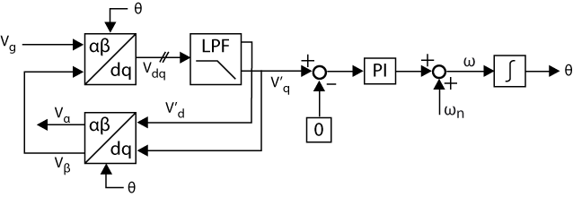
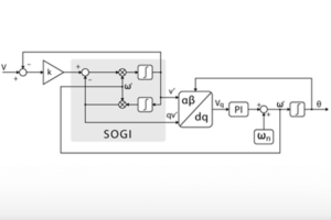
c) Second Order Generalized Integrator-PLL (SOGI-PLL)
The SOGI-PLL uses a band-pass filter tuned to the fundamental frequency, which introduces no delay, and a low-pass filter that produces a 90° phase shift to generate the in-quadrature signals. The main advantages of the SOGI-PLL are its good dynamic response, built-in harmonic filtering, and strong robustness under distorted grid conditions. However, it requires proper tuning of its parameters. More detailed information about this PLL, including its implementation in Simulink and PLECS, can be found in SOGI-PLL.
Comparison of the single-phase methods
Comparing these techniques, the T/4 transport delay PLL is the simplest and least computationally demanding, but its effective use is limited to scenarios with stable grid frequency and low distortion, conditions that are often not met in practice. The inverse Park transformation PLL offers improved filtering and phase accuracy, making it suitable for applications with moderate harmonic distortion, though its filtering delay and transient inaccuracies can impact dynamic performance.
Meanwhile, the SOGI-PLL stands out by combining fast dynamic response, robust harmonic rejection, and strong performance under grid disturbances, making it well-suited for real-world, variable, and weak grid conditions. Even if it is more complex and requires parameter tuning, its superior stability and accuracy often justify its adoption in modern single-phase inverter systems where grid quality cannot be guaranteed.
PLL-based methods for three-phase systems
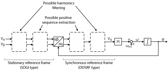
For three-phase systems, PLL-based techniques are easier to implement since all three phases are available for the αβ and dq transformations. The three most commonly used types of PLL in these systems are the synchronous reference frame-PLL (SRF-PLL) and two of its derivatives. These improved derivatives, namely the Double Decoupled SRF-PLL (DDSRF) and the Decoupled SOGI-PLL (DSOGI), offer enhanced robustness against unbalanced conditions due to their positive sequence estimation carried out in the stationary reference frame (αβ) or the rotating reference frame (dq).
The image below illustrates the potential modifications that can be made to the SRF-PLL to estimate the positive sequence and filter out harmonics.
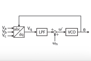
SRF-PLL
The corresponding structure is at the core and origin of most grid synchronization methods. It essentially corresponds to the basic PLL structure of Fig.2, using the quadrature voltage of the abc-dq transformation as phase-detector. It is simple and effective under normal operating conditions but can lose accuracy when disturbances occur. For more detailed information about this PLL, including its implementation in Simulink and PLECS, please refer to the SRF-PLL page.
DDSRF-PLL
This PLL is a modified SRF-PLL designed to decouple positive and negative sequences in the synchronous reference frame (dq). This enhancement improves the accuracy of parameter estimation under unbalanced grid voltage conditions. However, the decoupling of the axes involves low-pass filters, which inevitably slow down the PLL’s response. More detailed information about this PLL, including its implementation in Simulink and PLECS, can be found in DDSRF-PLL.
DSOGI-PLL
This PLL is a modified SRF-PLL that can estimate both positive and negative sequences in the stationary reference frame (αβ), while also filtering high and low-frequency distortions. An additional modification, the Multiple SOGI, further enhances its ability to filter specific harmonics. This implementation is possibly the most complex of all three, but also presents the most attractive performance (see below). More detailed information about this PLL, including its implementation in Simulink and PLECS, can be found in MSOGI-PLL.
Experimental comparison of the three-phase methods
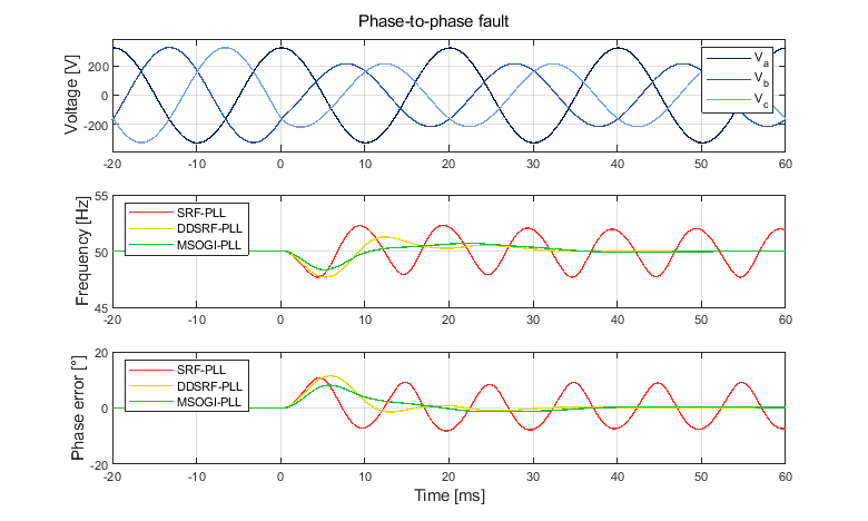
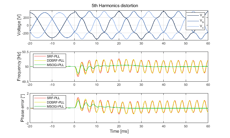
The three-phase grid synchronization methods mentioned above are compared below to observe their responses under disturbed conditions. For benchmarking purposes, disturbances will include i) a 60° phase jump, ii) a 2 Hz frequency jump, iii) 5th harmonic distortion with an amplitude of 0.1 p.u., and iv) a phase-to-phase fault in the grid.
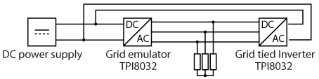
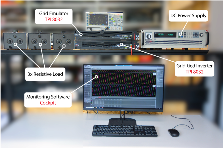
To test these grid synchronization methods, a grid emulator is used to replicate specific conditions, as these cannot be easily reproduced on a real grid. Here, the grid emulator and the grid-tied inverter are physically implemented using two TPI 8032 in a back-to-back configuration. This arrangement allows for the safe and reliable reproduction of disturbed conditions.
The experimental setup used for conducting these tests is presented below:
Using the experimental setup presented above, along with the downloadable files from the (DD)SRF-PLL and (M)SOGI-PLL pages, the obtained experimental results are displayed in the following graphs.
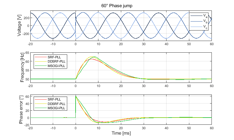
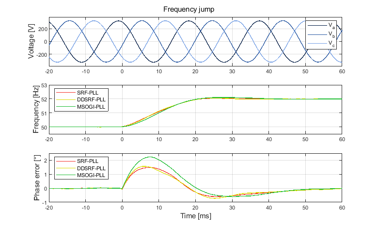
During single events such as a phase or frequency step, the three analyzed PLLs exhibit similar frequency and phase responses. However, the MSOGI-PLL suffers from a slightly longer settling time and larger overshoot during frequency steps. This is because SOGI filters utilize frequency feedback, unlike other PLLs.
Under unbalanced conditions, the basic SRF-PLL shows significant distortion in the phase and frequency estimates. The (M)SOGI-PLL and DDSRF-PLL do not exhibit this drawback, because they effectively reject the negative sequence, hence relying solely on the positive sequence for the phase and frequency estimation.
Finally, in the presence of harmonic distortion, the DDSRF and SRF PLLs show similarly distorted responses, as adding a decoupling stage does not affect the harmonics filtering. The MSOGI-PLL naturally behaves as a band-pass filter and includes a SOGI filter tuned to the 5th harmonic, further attenuating this specific harmonic.
In conclusion, the MSOGI-PLL satisfactorily mitigates a broader range of distortions over the DDSRF-PLL while maintaining a relatively simple implementation. An enhancement of the DDSRF-PLL that enables the decoupling of the zero, positive, and negative sequences, as well as harmonic attenuation, exists under the name HIHDO-PLL [5]. However, its implementation is considerably more complex.
Academic references
[1] H.S. Kamil, D.M. Said and M.W. Mustafa, “Recent advances in phase-locked loop based synchronization methods for inverter-based renewable energy sources,” in Indonesian Journal of Electrical Engineering and Computer Science, Vol. 18, No. 1, April 2020.
[2] M. Boyra and J. Thomas, “A review on synchronization methods for grid-connected three-phase VSC under unbalanced and distorted conditions,” in Proc. EPE Conf., Birmingham, 2011.
[3] M. Karimi-Ghartemani and M. R. Iravani, “A method for synchronization of power electronic converters in polluted and variable-frequency environments,” in IEEE Transactions on Power Systems, Vol. 19, Aug. 2004.
[4] R. Teodorescu, M. Liserre, and P. Rodriguez, “Chapter 4 – Grid Synchronization in Single-Phase Power Converters,” in Grid Converters for Photovoltaic and Wind Power Systems, John Wiley & Sons, 2011.
[5] Z. Ali, N. Christofides, L. Hadjidemetriou, and E. Kyriakides, “Design of an advanced PLL for accurate phase angle extraction under grid voltage HIHs and DC offset,” in IE Trans. Of Power Electronics, Vol. 11, No. 6, April 2018.