Table of Contents
Imperix controllers feature 4 clock generators, CLK0, CLK1, CLK2, and CLK3, which can be freely configured as derivatives of the 250 MHz base clock. These derivatives provide subsequent time bases for FPGA resources (such as ADCs and PWMs) and CPU events. However, as described in PN259, their behavior differs slightly:
- The main clock, CLK0, is mandatory and always active. It is used to trigger essential events such as the analog-to-digital conversion (ADC) and the launch of the CPU task. In Simulink and PLECS blocks, this clock generator is already embedded inside the CONFIG block. CLK0 only supports fixed-frequency operation.
- The clocks CLK1, CLK2, and CLK3 can be freely used as extra time bases for PWM resources. Unlike CLK0, these clocks support glitch-free reconfiguration during runtime, enabling variable-frequency operation. This capability is further described in PN121.
In stacked controller configurations (using imperix RealSync), all clock generators are intrinsically synchronized, with a guaranteed absolute maximum timing error of ±2 ns. Moreover, all the clock generators are reset at the same time, which implies that, if the frequency of one clock generator is a multiple of another, they are guaranteed to remain in phase (e.g., 20 kHz and 40 kHz).
More information on the timing architecture of imperix controllers is given in PN259.
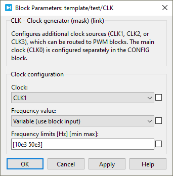
Simulink block
- The output can be connected to a PWM block input signal (marked with the symbol
>)to set its switching frequency. - CLK blocks only have a visible input if the
variablefrequency parameter is selected. This sets the clock frequency during runtime.
Standard parameters
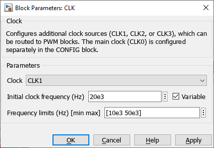
- The Clock ID selects which clock generator is used (CLK1, CLK2, or CLK3 only).
CLK0 is already used by the CONFIG block and cannot be instantiated as a separate clock block. - The initial clock frequency specifies the clock frequency in Hertz (Hz). If the desired frequency is not achievable (because of the limited resolution of 4 ns), the clock frequency is replaced by the closest achievable frequency, and a warning log message is generated in Cockpit.
The initial clock frequency value is overwritten by the input signal value during runtime if the frequency is configured as Variable.
Advanced parameters
- The Variable checkbox enables the reconfiguration of the frequency during runtime using the input signal.
- The Frequency limits set the minimal and maximal frequencies that the clock generator uses as saturation points.
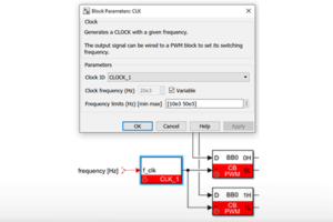
PLECS block
- The output can be connected to a PWM block input signal (marked with the symbol
>)to set its switching frequency. - The input is only visible if the frequency value is set as Variable. It sets the clock frequency at runtime.

Standard parameters
- The Clock ID selects which clock generator is used (CLK1, CLK2, or CLK3 only).
CLK0 is already used by the CONFIG block and cannot be instantiated as a separate clock block. - The Initial clock frequency sets the clock frequency in Hertz (Hz). If the desired frequency is not achievable (because of the peripheral resolution of 4 ns), the clock frequency is replaced by the closest achievable frequency, and a warning log message is generated in Cockpit.
The initial clock frequency value is overwritten by the input signal value during runtime if the frequency is configured as Variable.
Advanced parameters
- The Frequency value option can be set as Constant or Variable. Setting it as Variable enables the reconfiguration of the clock frequency during runtime.
- The Frequency limits set the minimal and maximal frequencies that the clock generator uses as saturation points.