Table of Contents
The GPI block (or its C++ routines) is responsible for reading the the logic states of the General Purpose Inputs (GPI) pins. This function allows the controller to read external digital signals efficiently.
Voltage logic levels, location and input counts are summarized in the reference table below, while detailed hardware specifications can be found within the associated product datasheet.
A comprehensive technical comparison of imperix’s programmable controllers is also provided in PN250.
| Param. | B-Box 4 | B-Box 3 | B-Box micro | B-Board 3 PRO |
|---|---|---|---|---|
| Location and count | – 24x VHDCI inputs | – 16x VHDCI inputs | – 8x PCB header inputs | – 16x PCB header inputs |
| Logic level | – 3.3V/5V | – 3.3V/5V | – 5V | – 3.3V |
| Shared with | – FLT | N/A | N/A | N/A |
| Product datasheet | B-Box 4 | B-Box 3 | B-Box micro | B-Board 3 PRO |
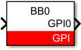
Simulink block
Signal specification
The output signal returns the value of one GPI pin.
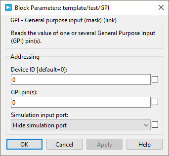
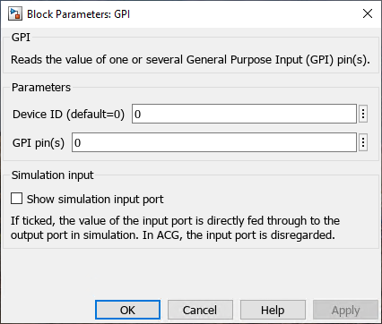
Parameters
Device IDselects which B-Box/B-Board to address when used in a multi-device configuration.GPI pin(s)(vectorizable) a selection of GPI pin(s) to read. It can be a single value or a vector.Show simulation input portdefines if the simulation input is displayed or not.
PLECS block
Signal specification
The output signal returns the value of one GPI pin.

Parameters
Device IDselects which B-Box/B-Board to address when used in a multi-device configuration.GPI pin(s)(vectorizable) a selection of GPI pin(s) to read. It can be a single value or a vector.Simulation input portdefines if the target inport is displayed or not. This parameter is only used in simulation.