Table of Contents
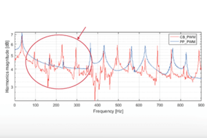
The FPGA-based PP-PWM (programmed pulse pattern) peripheral provides a specialized PWM scheme for two and three-level inverters, which relies on pre-computed pulse patterns. This type of modulation technique is often used to eliminate specific harmonics from the current spectrum. It is notably useful in applications that operate with a low pulse number, i.e. a low ratio between switching frequency and fundamental signal frequency.
The PP-PWM peripheral can be used for implementing all sorts of modulation techniques that rely on pre-computed pulse patterns, such as Selective Harmonic Elimination (SHE or SHEPWM) or other Optimized Pulse Patterns (OPPs).
The Programmed Pattern PWM module features the following characteristics:
- Three-phase output PWM for 2 and 3-level inverters
- A maximum of 16 switching angles per quarter period (64 angles per period)
- Angles update every quarter period
Similarly to other PWM modules, the following parameters of the PP PWM module can be configured:
- Complementary High and Low signals offer a configurable dead-time generation
- Programmed Pattern PWM outputs can be activated or deactivated during operation
Programmed Pattern PWM operation
To generate a PWM signal, the Programmed Pattern PWM module needs a set of switching angles between [0; \(\frac{\pi}{2}\)]. Thanks to the quarter-wave symmetry of the reference sinusoidal signal, only the angles for the first quarter of the sinewave are required. The angles for the three other quarters will be reconstructed by symmetry inside the FPGA peripheral.
Along with the angles, a vector of transitions with the same length as the angles vector is required. This vector of transition will specify for each angle, whether the switching signal will go “up or down”. A value of 1 encodes an upwards transition while a -1 encodes a downward transition. Two waveform examples for 2- and 3-level inverters are given below.
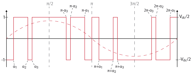
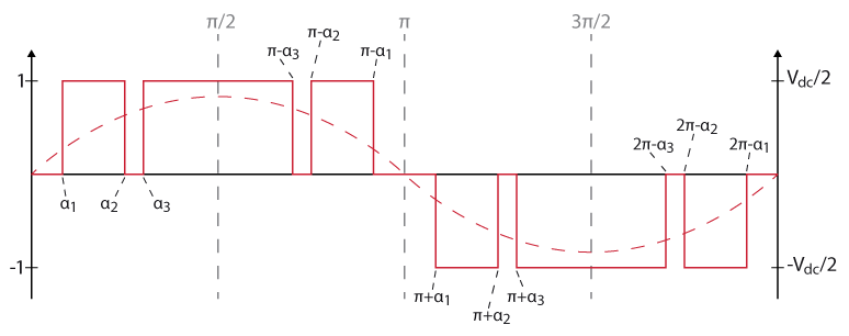
When comparing both waveforms, it can be noted that the 2-level waveform contains an additional transition in the middle of the period (angle = \(\pi\)) since a 2-level inverter cannot generate a zero voltage output.
At its output, the Programmed Pattern PWM module provides the gating signals and also indicates the current phase angle, for instance allowing for synchronization with the grid.
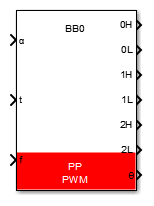
Simulink PP-PWM block
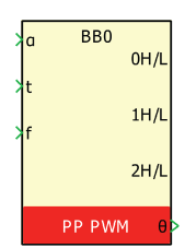
Signal specification
- The input \(\alpha\) contains the vector of angles between [0; \(\frac{\pi}{2}\)] that define the programmed pattern.
- The input signal
tis a vector containing the transitions for each angle. - The input signal
fdefines the pulse frequency. - The outputs are the generated PWM signals, according to the block configuration and the phase angle \(\theta\). The PWM outputs are only used for simulation.
- The phase angle output \(\theta\) is the phase angle for grid synchronization.
Parameters
Device IDselects which B-Box/B-Board to address when used in a multi-device configuration.Converter typeconfigures the programmed pattern PWM for a two or three-lvl inverter.Number of anglesconfigures the number of angles per quarter period.Show "activate" inputmakes theA(active) signal input visible. If not checked, the PP-PWM block is always active by default (once the controller outputs are enabled).Deadtime duration: configures the dead-time duration.
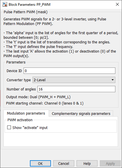
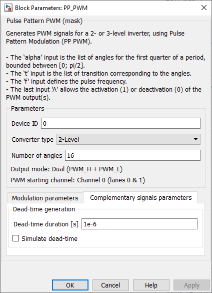
dead-time and show ”activate” input are common to all multilevel PWM blocks and are further documented on the PWM page.PLECS PP-PWM block
Signal specification
- The input \(\alpha\) contains the vector of angles between ]0; \(\frac{\pi}{2}\)[ that define the programmed pattern.
- The input signal
tis a vector containing the transitions for each angle. - The input signal
fdefines the pulse frequency. - The outputs are the generated PWM signals, according to the block configuration and the phase angle \(\theta\). The PWM outputs are only used for simulation.
- The phase angle output \(\theta\) is the phase angle for grid synchronization.
Parameters
Device IDselects which B-Box/B-Board to address when used in a multi-device configuration.Converter typeconfigures the programmed pattern PWM for a two or three-lvl inverter.Number of anglesconfigures the number of angles per quarter period.PWM activationmakes theA(active) signal input visible. If not checked, the PP-PWM block is always active by default (once the controller outputs are enabled).Deadtime duration: configures the dead-time duration.
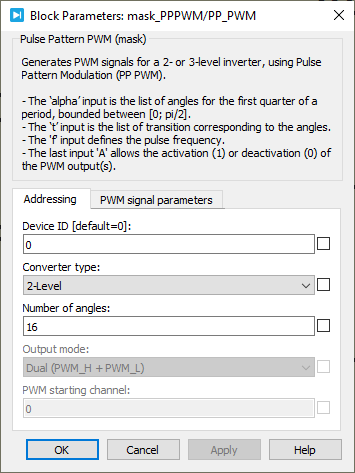
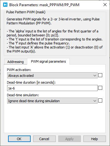
dead-time and show ”activate” input are common to all multilevel PWM blocks and are further documented on the PWM page.C++ functions
Specific to Programmed Pattern PWM
Functions common to all PWM drivers
These functions are common to all PWM blocks. Further documentation is available on the PWM page.