
Table of Contents
The Modbus_in block transmits data over Ethernet using the Modbus TCP protocol on TCP port 502. The block can be configured to operate in one of two modes:
- Master/Client: the controller actively sends write requests to a remote Slave/Server device.
- Slave/Server: the controller updates its own internal registers, making the data available for an external Master/Client device to read.
The block supports the Register types listed below.
| Register type | Access | Size |
|---|---|---|
| Discrete input | R | 1 bit (encoded as 1 byte, using the LSB) |
| Coil (discrete output) | R/W | 1 bit (encoded as 1 byte, using the LSB) |
| Input register | R | 16 bit (2 bytes) |
| Holding register | R/W | 16 bit (2 bytes) |
A concrete application example is presented in PN203, which runs a Modbus client on a TPI8032 and uses an external master on a computer.
To send data, use the Modbus_out block instead. Alternatively, for periodic transfers without explicit requests, especially at higher rates or with numerous variables, the Ethernet UDP input mailbox can be used instead.
Parameters
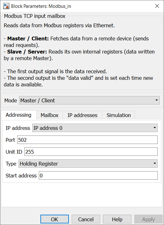
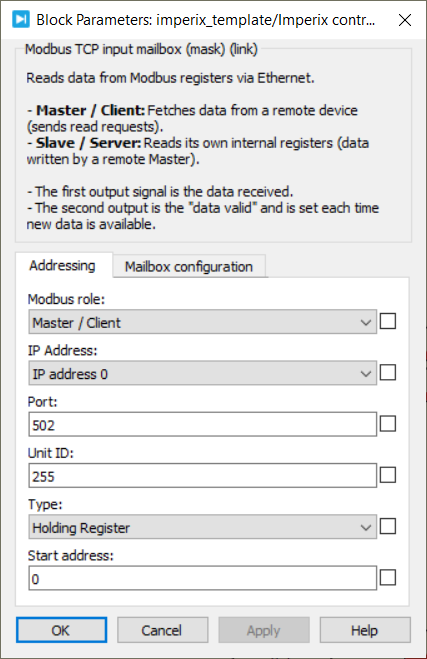
- Mode: Selects the mailbox’s operating mode (Master/Client or Slave/Server).
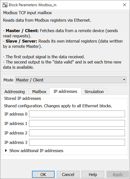
- IP Address (Master mode only): Selects the IP address to whom the data will be read.
- Port (Master mode only): Specifies the TCP port of the remote Modbus Slave/Server. The standard Modbus TCP port is
502. - Unit ID (Master mode only): Specifies the Modbus TCP Unit ID sent with requests to the remote device (
0–255). The default value is255. - Type: Selects the Modbus register type to read from
- Discrete input (Master mode only)
- Coil
- Input register (Master mode only)
- Holding register
- Start address: Sets the starting Modbus address for the range of registers to write (0–65535).
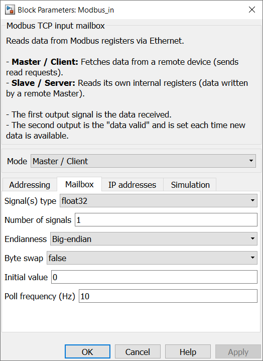
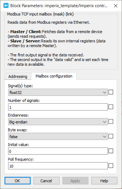
- Signal(s) type: Defines the data type of the input signal (int8, int16, int32, uint8, uint16, uint32, float32, or float64).
- Number of signals: Specifies the vector size of the data to be sent. The number of registers physically used is determined by the equivalent vector size in 16-bit words.
- Initial value: Sets the default output value.
- Poll frequency (Hz) (Master mode only): Defines the rate at which the controller polls the remote Modbus Slave for new data.
- Endianness (Master mode only): Defines the order of the 16-bit registers used to encode multi-register values.
- Byte swap (Master mode only): When enabled, swaps the two bytes inside each 16-bit register.
The four combinations of Byte order and swap produce the following byte sequences, where A is the most significant byte of a 32-bit value and D the least significant:
| Endianness | Byte swap | Sequence |
| Big-endian | false | ABCD |
| Big-endian | true | BADC |
| Little-endian | true | CDAB |
| Little-endian | false | DCBA |
In Slave/Server mode, the mailbox does not reorder registers; the application reads the raw register contents directly. Since imperix controllers use a little-endian CPU, multi-register values written directly by an external Master typically correspond to the CDAB (Little-endian, byte swap) layout.
Simulink block
Signal specification
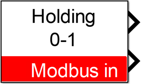
- The data output signal returns a vector containing the data read via Modbus TCP. Use the Number of signals parameter to set the vector length, and the Signal(s) type parameter to set the output data type.
- The second signal is the data valid output. It goes high each time new data arrives.
Mask
PLECS block
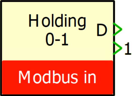
Signal specification
- The data output signal (D) returns a vector containing the data read via Modbus TCP. Use the Number of signals parameter to set the vector length, and the Signal(s) type parameter to set the output data type.
- The second signal is the data valid output. It goes high each time new data arrives.
Mask
The Ethernet IP addresses can be configured in the controller’s target window (Coder → Coder option → Target).
 By Jules Perrin • August 6, 2026 • PN203
 By Stéphane Lovejoy • April 2, 2021 • SD018