
Table of Contents
The Modbus_out block transmits data over Ethernet using the Modbus TCP protocol on TCP port 502. The block can be configured to operate in one of two modes:
- Master/Client: the controller actively sends write requests to a remote Slave/Server device.
- Slave/Server: the controller updates its own internal registers, making the data available for an external Master/Client device to read.
The block supports the Register types listed below.
| Register type | Access | Size |
|---|---|---|
| Discrete input | R | 1 bit (encoded as 1 byte, using the LSB) |
| Coil (discrete output) | R/W | 1 bit (encoded as 1 byte, using the LSB) |
| Input register | R | 16 bit (2 bytes) |
| Holding register | R/W | 16 bit (2 bytes) |
A concrete application example is presented in PN203, which runs a Modbus client on a TPI8032 and uses an external master on a computer.
To receive data, use the Modbus_in block instead. Alternatively, for periodic transfers without explicit requests, especially at higher rates or with numerous variables, the Ethernet UDP output mailbox can be used instead.
Parameters
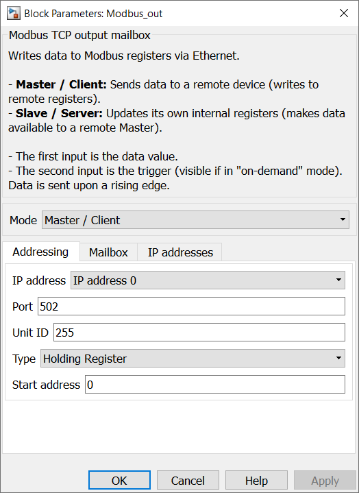
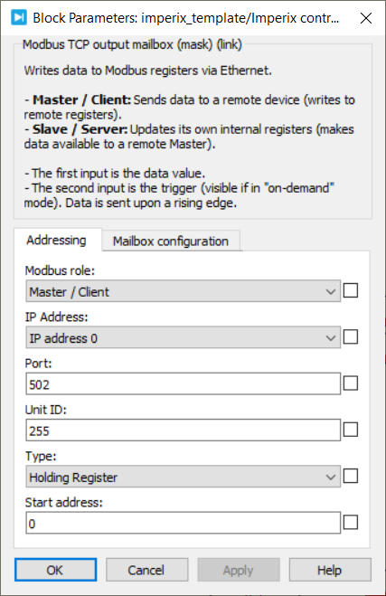
- Mode: Selects the mailbox’s operating mode (Master/Client or Slave/Server).
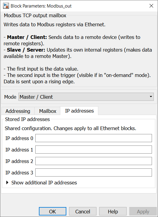
- IP Address (Master mode only): Selects the IP address to whom the data will be sent.
- Port (Master mode only): Specifies the TCP port of the remote Modbus Slave/Server. The standard Modbus TCP port is
502. - Unit ID (Master mode only): Specifies the Modbus TCP Unit ID sent with requests to the remote device (
0–255). The default value is255. - Type: Selects the Modbus register type to write to.
- Discrete input (Slave mode only)
- Coil
- Input register (Slave mode only)
- Holding register
- Start address: Sets the starting Modbus address for the range of registers to write (0–65535).
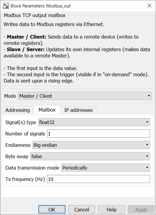
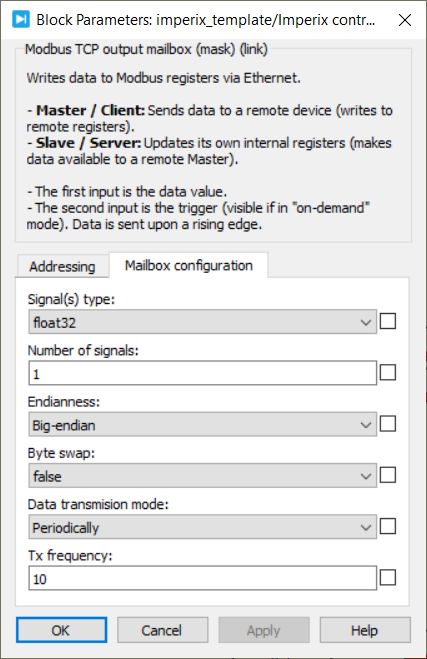
- Signal(s) type: Defines the data type of the input signal (int8, int16, int32, uint8, uint16, uint32, float32, or float64).
- Number of signals: Specifies the vector size of the data to be sent. The number of registers physically used is determined by the equivalent vector size in 16-bit words.
- Data transmission mode: Selects when the controller sends data.
- On-demand: The user manually triggers each transmission via the trigger input (at the rising edge).
- Periodically: The controller sends data at a fixed rate, regardless of whether the data has changed.
- Tx frequency (Hz): Defines the transmission rate in Hz (only relevant in Periodically mode).
- Endianness (Master mode only): Defines the order of the 16-bit registers used to encode multi-register values.
- Byte swap (Master mode only): When enabled, swaps the two bytes inside each 16-bit register.
The four combinations of Byte order and swap produce the following byte sequences, where A is the most significant byte of a 32-bit value and D the least significant:
| Endianness | Byte swap | Sequence |
| Big-endian | false | ABCD |
| Big-endian | true | BADC |
| Little-endian | true | CDAB |
| Little-endian | false | DCBA |
In Slave/Server mode, the mailbox does not reorder registers; the application writes the raw register contents directly. Since imperix targets use a little-endian CPU, multi-register values written directly by the application typically correspond to the CDAB (Little-endian, byte swap) layout.
Simulink block
Signal specification
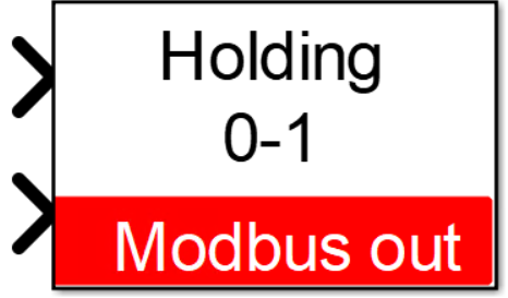
- The data input accepts a vector containing the data to write via Modbus TCP. Use the Number of signals parameter to set the vector length, and the Signal(s) type parameter to set the input data type.
- The second input is the trigger (only visible in “on-demand” mode). The block sends data on a rising edge of this signal.
Mask
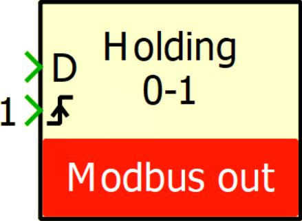
PLECS block
Signal specification
- The data input (D) accepts a vector containing the data to write via Modbus TCP. Use the Number of signals parameter to set the vector length, and the Signal(s) type parameter to set the input data type.
- The second input is the trigger (only visible in “on-demand” mode). The block sends data on a rising edge of this signal.
Mask
The Ethernet IP addresses can be configured in the controller’s target window (Coder → Coder option → Target).
 By Jules Perrin • August 6, 2026 • PN203
 By Stéphane Lovejoy • April 2, 2021 • SD019