Table of Contents
The hall sensor interface (HAL) block provides access to the commutation signals from Hall effect sensors of a brushless DC motor.
The B-Box RCP supports up to two machines with Hall sensors through the Motor Interface for B-Box RCP. Hall sensors are usually found in three-phase brushless DC machines and provide a 60° resolution on the rotor mechanical position. The hall sensor block provides the commutation signals for the A, B, and C phases. The control algorithm can use these signals to implement a six-step commutation method.
The HAL block is available starting from version 3.7.1.4 of the SDK. The Motor Interface for B-Box RCP is required to use this driver.
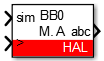
Simulink block
Signal specification
- The output signal is a vector containing the A, B, and C signals (Booleans)
- The
siminput vector is used in simulation and represents the actual commutation signals, computed by the simulation plant model. - The
>input signal needs to be connected to the sampling clock generated by the CONFIG block to account for the exact sampling instant in simulation.
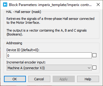
Parameters
Device IDselects which B-Box/B-Board to address when used in a multi-device configuration.Motor Interface inputselects which connector of the Motor Interface is used as an input.
PLECS block
Signal specification
- The output signal is a vector containing the A, B, and C signals (Booleans)
- The
siminput vector is used in simulation and represents the actual commutation signals, computed by the simulation plant model. - The
>input signal needs to be connected to the sampling clock generated by the CONFIG block to account for the exact sampling instant in simulation.

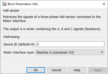
Parameters
Device IDselects which B-Box/B-Board to address when used in a multi-device configuration.Motor Interface inputselects which connector of the Motor Interface is used as an input.