Table of Contents
The EnDat block instantiates an EnDat master to communicate with compatible digital encoders and similar digital sensors, typically in motor drive applications.
This block is only compatible with the B-Box4, which provides two RS-485-based serial ports (SERIAL A and SERIAL B). Both ports can interface with sensors using three widely adopted communication protocols: SSI, BiSS-C and EnDat2.2 (this page).
EnDat protocol in a nutshell
The EnDat protocol is a master-slave serial interface standard developed by HEIDENHAIN and widely used in industrial applications.
Similarly to SSI and BiSS-C, the interface is composed of two signals, CLOCK (driven by the master) and DATA (bidirectional), regardless of the resolution (i.e., number of bits per revolution) of the sensor. Differential signaling improves the noise immunity and allows for longer cable runs, making it suitable for industrial environments. Starting from version 2.2, EnDat supports propagation delay compensation and a clock frequency up to 16MHz, therefore faster than SSI or BiSS-C.
EnDat provides room for a control mechanism to access the slave’s configuration memory and transmits special commands. However, this mechanism significantly increases complexity and is currently not supported in the imperix implementation.
Strengths and limitations
Similarly to SSI and BiSS-C, EnDat can be easily integrated and performs reliably even in electrically noisy environments. The synchronous data transfer provides accurate, low-latency position feedback, making it well suited for real-time control. It supports higher clock frequencies (up to 16 MHz) and allows for the compensation of the propagation delay.
Simulink block
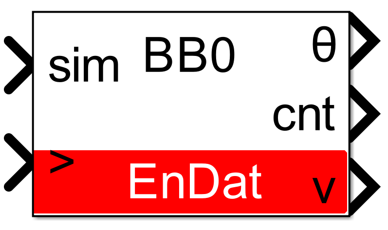
Signal specification
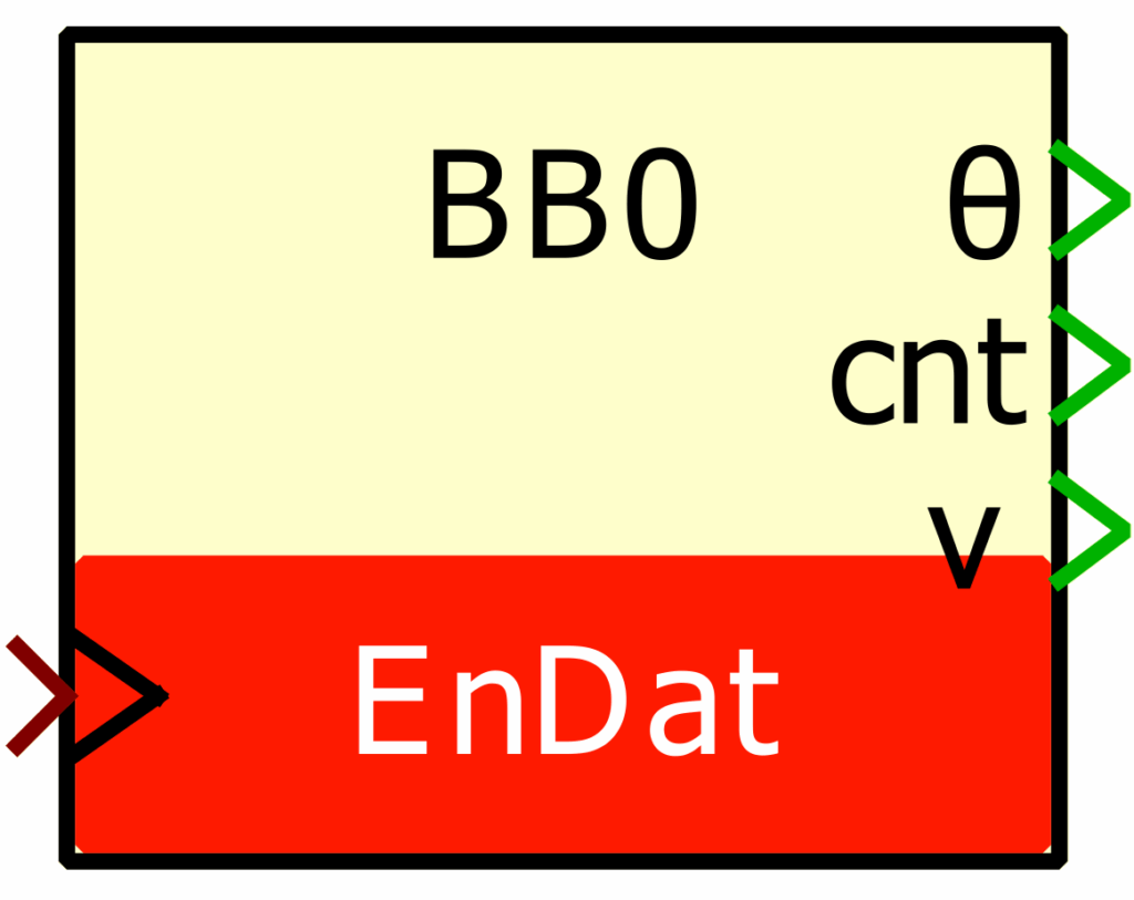
- The output θ is the single-turn position, in radians, in [0, 2π].
- The output
cntis the multi-turn counter, as received from the sensor. This port is hidden by default but it can be shown using theOutput multi-turn countercheckbox. - The output
vis the valid data signal, set to 1 each time new data are available. - The input
simis a 2-dimensional vector used in simulation and represents the angle value (in radians) and multi-turn counter (-) computed by the simulation plant model. - The
>input signal needs to be connected to the sampling clock generated by the CONFIG block.
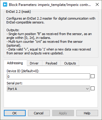
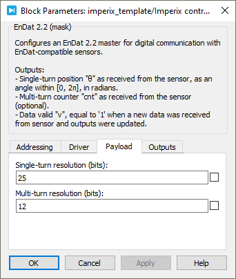
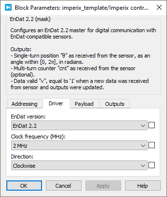
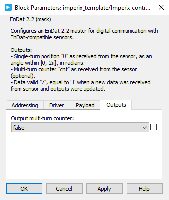
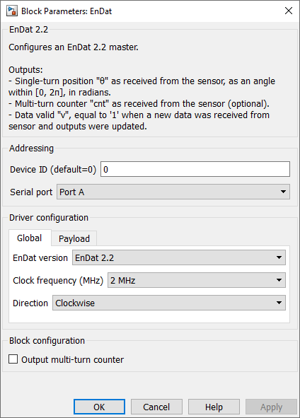
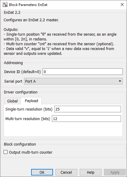
Parameters
Device IDselects which device to address when used in a multi-device configuration.Serial portselects the serial port.EnDat versionspecifies the EnDat version of the sensor, either EnDat 2.2 or EnDat 2.1.Clock frequencyspecifies the transmission clock frequency for the BiSS-C communication, in MHz. The clock frequency cannot exceed 10 MHz, as defined by the BiSS-C standard.Directionspecifies the direction as clockwise or counterclockwise. When counterclockwise is selected, the output angle θ is 2π-θ’, where θ’ is the angle received from the sensor.Single-turn resolutionspecifies the resolution (i.e., number of bits) for the single-turn position. The single-turn resolution cannot exceed 32 bits.Multi-turn resolutionspecifies the resolution (i.e., number of bits) for the multi-turn counter. The multi-turn resolution cannot exceed 32 bits.Output multi-turn countershows or hides the multi-turn counter outputcnt.
PLECS block
Signal specification
- The output θ is the single-turn position, in radians, in [0, 2π].
- The output
cntis the multi-turn counter, as received from the sensor. This port is hidden by default but it can be shown using theOutput multi-turn countercheckbox. - The output
vis the data valid signal, set to 1 each time a new data are available. - The input
simis a 2-dimensional vector used in simulation and represents the angle value (in radians) and multi-turn counter (-) computed by the simulation plant model. - The
>input signal needs to be connected to the sampling clock generated by the CONFIG block.
Parameters
Device IDselects which device to address when used in a multi-device configuration.Serial portselects the serial port.EnDat versionspecifies the EnDat version of the sensor, either EnDat 2.2 or EnDat 2.1.Clock frequencyspecifies the transmission clock frequency for the BiSS-C communication, in MHz. The clock frequency cannot exceed 10 MHz, as defined by the BiSS-C standard.Directionspecifies the direction as clockwise or counterclockwise. When counterclockwise is selected, the output angle θ is 2π-θ’, where θ’ is the angle received from the sensor.Single-turn resolutionspecifies the resolution (i.e., number of bits) for the single-turn position. The single-turn resolution cannot exceed 32 bits.Multi-turn resolutionspecifies the resolution (i.e., number of bits) for the multi-turn counter. The multi-turn resolution cannot exceed 32 bits.Output multi-turn countershows or hides the multi-turn counter outputcnt.