Table of Contents
The SSI block instantiates a Synchronous Serial Interface (SSI) master to communicate with SSI-compatible digital encoders and similar digital sensors, typically in motor drive applications.
This block is only compatible with the B-Box4, which provides two RS-485-based serial ports (SERIAL A and SERIAL B). Both ports can interface with sensors using three widely adopted communication protocols: SSI (this page), BiSS-C and EnDat2.2.
Along with the single-turn position, this block supports the reception of a multi-turn counter and follows the common assumption that the single-turn and multi-turn values are placed side by side in the frame received from the sensor, as illustrated below.
As the SSI protocol does not define separate versions, this driver is compatible with any sensor that uses binary-encoded SSI. Gray encoding is currently not supported.
SSI protocol in a nutshell
The SSI protocol is a master-slave serial interface standard created by Max Stegmann GmbH in 1984. Nowadays, it is widely used in industrial applications. Designed for a single master and a single slave, the SSI protocol creates a direct, point-to-point communication link.
The interface is composed of two unidirectional signals, CLOCK (driven by the master) and DATA (driven by the slave), regardless of the resolution (i.e., number of bits per revolution) of the sensor. Differential signaling improves the noise immunity and allows for longer cable runs, making it suitable for industrial environments.
The transmission of a frame starts when the controller (master) starts the CLOCK. Then, the sensor (slave) sends back the data – usually the encoder position – bit by bit on DATA, synchronously with the CLOCK. The transmission ends by the time-out (DATA signal maintained to LOW by the slave) and the pause (mandatory idle state before the next transmission starts).
The angle within the current rotation is usually called single-turn position. Most digital encoders also offer the capability to track the number of rotations, usually referred to as multi-turn counter.
Strengths and limitations
The SSI protocol is valued for its simple and robust design. With only two differential digital lines, it can be easily integrated and performs reliably even in electrically noisy environments. The synchronous data transfer provides accurate, low-latency position feedback, making it well suited for real-time control.
On the downside, SSI is a one-way protocol with no automatic configuration or diagnostic capability. The master must know the frame structure of the sensor, and the maximum cable length decreases as the clock frequency increases.
Simulink block
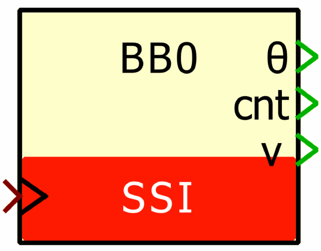
Signal specification
- The θ output is the single-turn position, in radians, in [0, 2π].
- The
cntoutput is the multi-turn counter, as received from the sensor. This port is hidden by default but it can be shown using theOutput multi-turn countercheckbox. - The
voutput is the data valid signal, set to 1 each time a new data are available. - The
siminput is a 2-dimensional vector used in simulation and represents the angle value (in radians) and multi-turn counter (-) computed by the simulation plant model. - The
>input signal needs to be connected to the sampling clock generated by the CONFIG block.
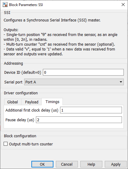
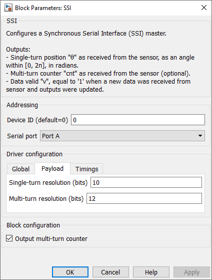
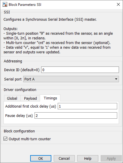
Parameters
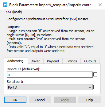
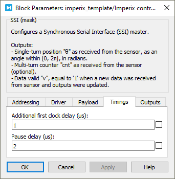
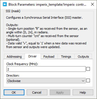
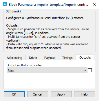
Device IDselects which device to address when used in a multi-device configuration.Serial portselects the serial port.Clock frequencyspecifies the transmission clock frequency for the SSI communication, in MHz. The clock frequency cannot exceed 2 MHz, as defined by the SSI standard.Directionspecifies the direction as clockwise or counterclockwise. When counterclockwise is selected, the output angle θ is 2π-θ’, where θ’ is the angle received from the sensor.Single-turn resolutionspecifies the resolution (i.e., number of bits) for the single-turn position. The single-turn resolution cannot exceed 32 bits.Multi-turn resolutionspecifies the resolution (i.e., number of bits) for the multi-turn counter. The multi-turn resolution cannot exceed 32 bits.Additional first clock delayspecifies the delay, in us, added to the first half clock period.Pause delayspecifies the duration, in us, of the recovery time after each transmission.Output multi-turn countershows or hides the multi-turn counter outputcnt.
PLECS block
Signal specification
- The θ output is the single-turn position, in radians, in [0, 2π].
- The
cntoutput is the multi-turn counter, as received from the sensor. This port is hidden by default but it can be shown using theOutput multi-turn countercheckbox. - The
voutput is the data valid signal, set to 1 each time a new data are available. - The
siminput is a 2-dimensional vector used in simulation and represents the angle value (in radians) and multi-turn counter (-) computed by the simulation plant model. This input is visible in the parent level. - The
>input signal needs to be connected to the sampling clock generated by the CONFIG block.
Parameters
Device IDselects which device to address when used in a multi-device configuration.Serial portselects the serial port.Clock frequencyspecifies the transmission clock frequency for the SSI communication, in MHz. The clock frequency cannot exceed 2 MHz, as defined by the SSI standard.Directionspecifies the direction as clockwise or counterclockwise. When counterclockwise is selected, the output angle θ is 2π-θ’, where θ’ is the angle received from the sensor.Single-turn resolutionspecifies the resolution (i.e., number of bits) for the single-turn position. The single-turn resolution cannot exceed 32 bits.Multi-turn resolutionspecifies the resolution (i.e., number of bits) for the multi-turn counter. The multi-turn resolution cannot exceed 32 bits.Additional first clock delayspecifies the delay, in us, added to the first half clock period.Pause delayspecifies the duration, in us, of the recovery time after each transmission.Output multi-turn countershows or hides the multi-turn counter outputcnt.