Table of Contents
The BiSS-C block instantiates a Bidirectional Synchronous Serial – Communication (BiSS-C) master to communicate with BiSS-C-compatible digital encoders and similar digital sensors, typically in motor drive applications.
This block is only compatible with the B-Box4, which provides two RS-485-based serial ports (SERIAL A and SERIAL B). Both ports can interface with sensors using three widely adopted communication protocols: SSI, BiSS-C (this page) and EnDat2.2.
Along with the single-turn position, this block supports the reception of a multi-turn counter and follows the common assumption that the single-turn and multi-turn values are placed side by side in the frame received from the sensor, as illustrated below.
(ACK) = acknowledgment bit ; (start) = start bit ; (CDM/S) = control data master/slave
As the BiSS-C protocol does not define separate versions, this driver is compatible with any sensor that uses binary-encoded BiSS-C. Gray encoding is currently not supported.
BiSS-C protocol in a nutshell
Created in 2002 by iC Haus GbmH, the BiSS-C protocol is a master-slave serial standard widely used in industrial applications. Often considered as an extension to SSI, the BiSS-C protocol supports a higher clock frequency (up to 10 MHz) and propagation delay compensation.
The interface is composed of two unidirectional signals, CLOCK (driven by the master) and DATA (driven by the slave), regardless of the resolution (i.e., number of bits per revolution) of the sensor. Differential signaling improves the noise immunity and allows for longer cable runs, making it suitable for industrial environments.
As illustrated above, the frame transmission consists of the following steps:
- The controller (master) initiates the transmission by starting the CLOCK.
- The sensor (slave) acknowledges by driving DATA signal to LOW on the second rising edge of the CLOCK (see ‘ack’ on the figure). This mechanism allows the master to estimate the total propagation delay by comparing the CLOCK and DATA edges.
- When needed, the slave can maintain the DATA signal to LOW for several CLOCK cycles, to sample the position or for internal computations for instance (see ‘slave proc. time’).
- The slave triggers the payload transmission by sending the start bit (see ‘start’).
- The first bit of the payload is the slave-to-master control data bit (see ‘CDS’).
- The slave transmits the payload, bit by bit on DATA, synchronously with the CLOCK.
- At the end of the transmission, the slave maintains the DATA signal to LOW during the time-out. The master can optionally send a master-to-slave control data bit at this moment.
- The CLOCK and DATA return to IDLE.
The BiSS-C protocol provides room for a control mechanism to access the slave’s configuration memory. However, since the control bits are distributed across multiple frames—with only two control bits per frame (see “CDM” and “CDS”)—this mechanism significantly increases complexity and is currently not supported in the imperix implementation.
The angle within the current rotation is usually called single-turn position. Most digital encoders also offer the capability to track the number of rotations, usually referred to as multi-turn counter.
Strengths and limitations
The BiSS-C protocol is valued for its simple and robust design. With only two differential and unidirectional digital lines, it can be easily integrated and performs reliably even in electrically noisy environments.
The synchronous data transfer provides accurate, low-latency position feedback, making it well suited for real-time control. Moreover, it supports higher clock frequencies (up to 10 MHz) and allows the compensation of the propagation delay.
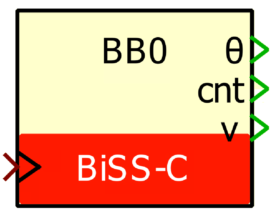
Simulink block
Signal specification
- The output θ is the single-turn position, in radians, in [0, 2π].
- The output
cntis the multi-turn counter, as received from the sensor. This port is hidden by default but it can be shown using theOutput multi-turn countercheckbox. - The output
vis the data valid signal, set to 1 each time a new data are available. - The input
simis a 2-dimensional vector used in simulation and represents the angle value (in radians) and multi-turn counter (-) computed by the simulation plant model. - The
>input signal needs to be connected to the sampling clock generated by the CONFIG block.
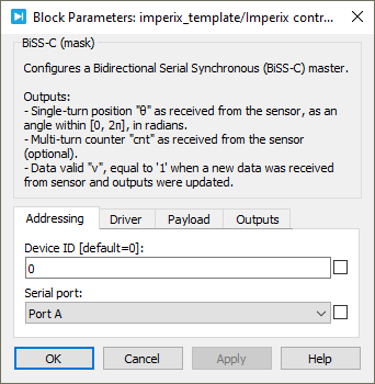
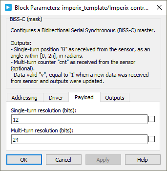
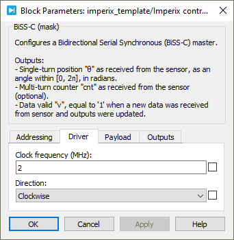
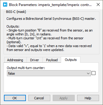
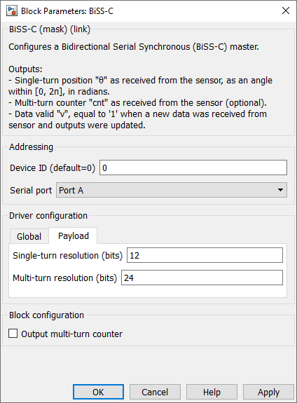
Parameters
Device IDselects which device to address when used in a multi-device configuration.Serial portselects the serial port.Clock frequencyspecifies the transmission clock frequency for the BiSS-C communication, in MHz. The clock frequency cannot exceed 10 MHz, as defined by the BiSS-C standard.Directionspecifies the direction as clockwise or counterclockwise. When counterclockwise is selected, the output angle θ is 2π-θ’, where θ’ is the angle received from the sensor.Single-turn resolutionspecifies the resolution (i.e., number of bits) for the single-turn position. The single-turn resolution cannot exceed 32 bits.Multi-turn resolutionspecifies the resolution (i.e., number of bits) for the multi-turn counter. The multi-turn resolution cannot exceed 32 bits.Output multi-turn countershows or hides the multi-turn counter outputcnt.
PLECS block
Signal specification
- The output θ is the single-turn position, in radians, in [0, 2π].
- The output
cntis the multi-turn counter, as received from the sensor. This port is hidden by default but it can be shown using theOutput multi-turn countercheckbox. - The output
vis the data valid signal, set to 1 each time a new data are available. - The input
simis a 2-dimensional vector used in simulation and represents the angle value (in radians) and multi-turn counter (-) computed by the simulation plant model. - The
>input signal needs to be connected to the sampling clock generated by the CONFIG block.
Parameters
Device IDselects which device to address when used in a multi-device configuration.Serial portselects the serial port.Clock frequencyspecifies the transmission clock frequency for the BiSS-C communication, in MHz. The clock frequency cannot exceed 10 MHz, as defined by the BiSS-C standard.Directionspecifies the direction as clockwise or counterclockwise. When counterclockwise is selected, the output angle θ is 2π-θ’, where θ’ is the angle received from the sensor.Single-turn resolutionspecifies the resolution (i.e., number of bits) for the single-turn position. The single-turn resolution cannot exceed 32 bits.Multi-turn resolutionspecifies the resolution (i.e., number of bits) for the multi-turn counter. The multi-turn resolution cannot exceed 32 bits.Output multi-turn countershows or hides the multi-turn counter outputcnt.