Table of Contents
While imperix controllers are typically programmed with applications built in Simulink or PLECS, imperix also provides direct access to FPGA resources through its FPGA development environment, known as the sandbox.
This level of access enables a wide range of applications, including direct control of the controller transceivers and the implementation of Aurora communication over the physical SFP ports. Such flexibility makes it well suited to accommodate the diverse Aurora configurations used by major simulator vendors, such as OPAL-RT, Plexim, Typhoon and RTDS.
This page explains how to set up this communication by combining a user application running on the CPU with additional logic in the FPGA bitstream. For a quick and straightforward integration, a ready-to-use user application template is provided, along with generation scripts to easily generate the bitstreams for several vendors.
SFP, Aurora and imperix
With three Small Form-factor Pluggable (SFP) ports, the imperix controllers are naturally built for multi-device topologies, such as wide multi-master and master-slave RealSync networks.
To fully leverage these high-speed SFP connections, the Aurora protocol from Xilinx provides a lightweight, high-throughput protocol. By using native transceivers with minimal overhead, Aurora delivers low latency and near line-rate performance without the complexity of protocols like Ethernet, making it an efficient and practical choice for high-bandwidth, point-to-point links.
Although simple, Aurora requires identical configurations at both ends of the link. This usually makes interoperability between devices from different vendors challenging.
Through the sandbox, its FPGA development environment, imperix provides unrestricted access to the SFP ports of its controllers. This allows instantiating a configurable Aurora IP and implement the required logic to match the configuration and frame structure of any third-party manufacturer.
For a quick start, synthesis-ready Vivado projects are provided for several vendors such as OPAL-RT, Plexim, Typhoon and RTDS. These projects implement the FPGA logic depicted in the next section, including an Aurora IP with the same configuration as the targeted third-party simulator, a driver to encode and decode the Aurora frames, and SBI/SBO registers to exchange data with the user application running in the CPU.
Setup overview
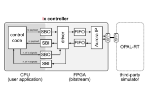
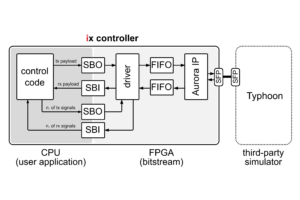
The setup considered to exchange data with a third-party device is depicted below. It is composed of three main parts: the user application, the FPGA bitstream and the third-party application.
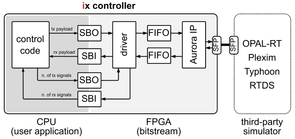
The user application is running in the CPU of the imperix controller and contains the code designed by the user, typically a control algorithm. This application has no special requirements, except that it contains SBO blocks to send data to the driver and SBI blocks to access incoming data from the SFP connection.
The FPGA bitstream defines the logic executed on the imperix controller’s FPGA. Together with the controller firmware, it implements the functionality required for Aurora communication. The core components of this communication are the driver, FIFOs and the Xilinx Aurora IP:
- The driver receives the outgoing data from the user application through the SBO blocks, packages it into frames compatible with the third-party simulator and transfers the frames to the Aurora IP. In parallel, it receives incoming frames from the Aurora IP, decodes them and makes the values available to the user application via SBI blocks.
- The FIFOs are essential for the clock domain crossing. They bridge the main clock domain of imperix controllers, running at 250 MHz, to the clock domain of the Aurora IP. The frequency of the Aurora IP depends on the configuration of the Aurora channel and is therefore different for each vendor.
- The Aurora IP is provided by Xilinx. As explained in the presentation page, the IP enables easy implementation of transceivers while providing a light-weight user interface on top of which designers can build a serial link.
Because major market vendors use different Aurora channel configurations and, in some cases, specific frame structures, the bitstream is vendor-specific and must be generated using the corresponding generation scripts.
Finally, the third-party application runs on a third-party device and is not directly related to imperix products. In this example, it is required that the application enables an Aurora communication on an SFP port of the third-party simulator.
Supported devices
The supported devices are listed below. Devices marked in bold have been expressly tested and validated.
| Vendor | Compatible devices | Related page(s) |
|---|---|---|
| OPAL-RT | OP4510, OP4512 | Aurora link with OPAL-RT via SFP |
| Plexim | RT-Box 1, RT-Box 2, RT-Box 3 | Aurora link with Plexim via SFP |
| Typhoon | HIL101, HIL404, HIL506, HIL606 | Aurora link with Typhoon via SFP |
| RTDS | GTSOC V2 | SFP communication with an RTDS MMC simulator (*) |
(*) The communication chain, driver and address mapping implemented in this page are very specific in order to match the frame structure expected by the MMC model running on the GTSOC V2.

The Aurora configuration applied by each vendor is summarized in the following table.
| Vendor | Aurora protocol | Line rate (Gbps) | Endianness | CRC check | Frame structure |
|---|---|---|---|---|---|
| OPAL-RT | Aurora 8B10B | 5 | Little | Yes | – |
| Plexim | Aurora 64B66B | 6.25 | Big | Yes | Custom |
| Typhoon | Aurora 8B10B | 5 | Big | No | – |
| RTDS | Aurora 8B10B | 2 | Little | No | Custom |
User application template
As mentioned, the user application has no special requirements, except that it contains SBO and SBI blocks to communicate with the driver running in the FPGA.
For a quick start, a user application template, either in Simulink or PLECS, that sends and receives three signals via SFP is provided below:
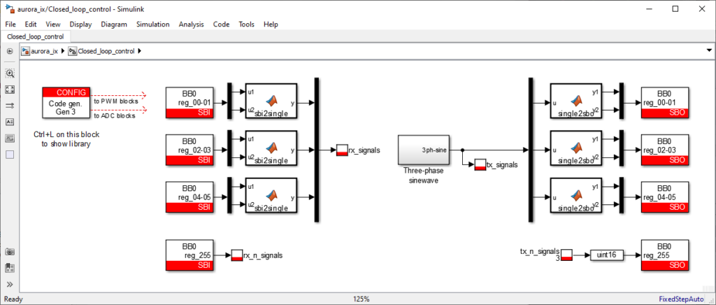
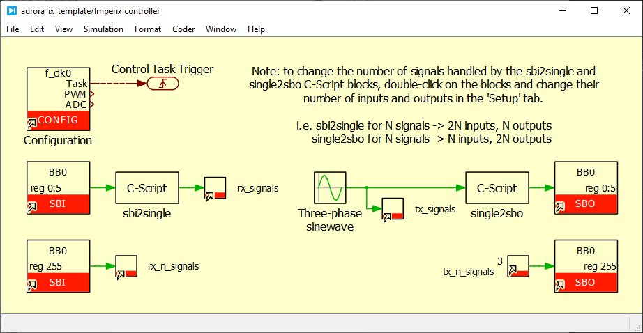
The communication between the CPU and the FPGA is handled by the SBIO bus. Thanks to the related SBI and SBO blocks, the CPU generates read and write requests on the SBIO bus and interacts with the registers located in the FPGA.
As the SBIO bus is intended to carry 16-bit data, the 32-bit values are split into two 16-bit words to be transferred over the bus. The conversion is handled by the single2sbo and sbi2single Matlab/C-Script functions.
To build the user application, make sure that the Automated Code Generation mode is selected in the CONFIG block and press Ctrl+B (Simulink) or Ctrl+Alt+B and then Build (PLECS).
Bitstream generation
To generate the bitstream running in the imperix controller, please follow the steps outlined below:
- Install the Vivado Design Suite (version 2022.1 is recommended). The step-by-step installation procedure is detailed in Installation of AMD Xilinx Vivado Design Suite.
- Download the imperix source files (version 3.10 Rev. 0 or later is mandatory). The source files are available for free at Download of the imperix firmware IP for FPGA sandbox.
- Download the generation scripts corresponding to the targeted vendor in the table below and follow this procedure to generate the bitstream from the scripts.
| Vendor | Compatible devices | Generation scripts |
| OPAL-RT | OP4510, OP4512 | aurora_ix_opalrt_gen_scripts.zip |
| Plexim | RT-Box 1, RT-Box 2, RT-Box 3 | aurora_ix_plexim_gen_scripts.zip |
| Typhoon | HIL101, HIL404, HIL506, HIL606 | aurora_ix_typhoon_gen_scripts.zip |
Startup procedure
To start using the setup and exchange data with the third-party device:
- Connect the imperix controller to the third-party simulator with an SFP cable. By default, the Aurora communication is connected to the port SFP 0 (UP) on the controller.
- Generate the bitstream, as explained in the dedicated section above.
- Load the bitstream on the imperix controller via Cockpit.
- Download the user application template in Simulink or PLECS (or use your own model). If you use your own model, it is recommended to add probes on the exchanged signals as in the provided user application.
- Build the model and launch it on the imperix controller via Cockpit.
- Compile/build the code for the third-party simulator and launch it.
Applications are provided for several vendors in the pages listed in the Supported devices section above. Refer to the vendor’s documentation for advanced guidance and details. - Use Cockpit to monitor the exchanged signals.
Address mapping
As introduced in the setup overview, the internal CPU-FPGA communication in imperix controllers is managed by the SBIO bus.
Since they correspond to 16-bit words, SBI and SBO addresses are grouped by two to transfer the 32-bit words of the payload, starting at address 0. For instance, the first word to be transmitted must be written in the SBO 1 (MSB) and SBO 0 (LSB), and the first word received from the simulator is available in SBI 1 (MSB) and SBI 0 (LSB).
The number of signals to transmit to the third-party device must be specified in SBO 255. Similarly, the number of received signals is available in SBI 255.
| SBO address | Transmitted signals (tx payload) | SBI address | Received signals (rx payload) | ||
|---|---|---|---|---|---|
| 1 | 0 | tx_signal_00 | 1 | 0 | rx_signal_00 |
| 3 | 2 | tx_signal_01 | 3 | 2 | rx_signal_01 |
| … | … | ||||
| 63 | 62 | tx_signal_31 | 63 | 62 | rx_signal_31 |
| (free for extension) | (free for extension) | ||||
| – | 255 | n_tx_signals | – | 255 | n_rx_signals |
To go further
How to exchange more signals
The current implementation supports the exchange of 32 signals in each direction. This section describes how to extend the number of signals.
- Change the number of ports of the provided VHDL driver.
The driver is located in<folder>/hdl/sfp_aurora_rtbox.vhdand the instructions are clearly indicated at the top of the file. These changes consist of adding more ports, inserting them into the interfaces, and linking their values to the two internal arrays. - Adapt the surrounding modules.
Make sure that the surrounding modules support the desired number of signals, namely thesbio_256_registers,convert_16b_to_32bandconvert_32b_to_16bmodules. Do not forget to extend the length of the axis_data_fifo_0 FIFO. - Regenerate the bitstream.
- Adapt the Simulink model.
Add the corresponding SBI and SBO blocks in the Simulink model. - Make sure that the third-party device is configured accordingly.
How to assign a different SFP port
In the provided implementation, the communication with the RT-Box is configured on the SFP port 0 (UP). To assign the SFP communication to another SFP port (e.g., SFP 1 (DOWN0)):
- Open the Vivado project.
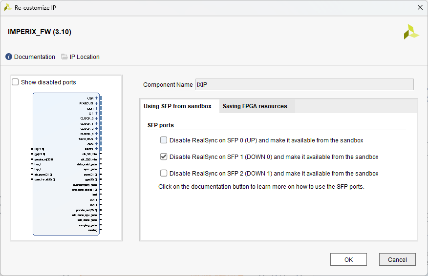
- Change the enabled SFP port.
Double-click on the IX IP block in the block diagram to open the configuration panel. Once opened, in the Using SFP from sandbox tab, check the entry of the desired SFP port and uncheck the entry for SFP 0.
This will re-enable RealSync on port 0 (UP)and disable it on the selected port, removing the txn_0, txp_0, rxn_0, rxp_0 ports of the imperix firmware IP and exposing the ports of the selected SFP port instead.
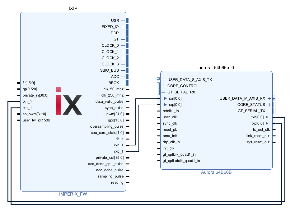
- Connect the ports.
Connect the four ports exposed during step 3 to the Aurora IP, as illustrated below.
- Regenerate the bitstream.