Table of Contents
Switching ripple filters are commonly added to grid-connected voltage source converters (VSCs) to filter out undesirable switching harmonics from the VSC’s output voltage. LCL filters are chosen due to their superior harmonic attenuation behavior and reduced size and cost when compared to L and LC filters. Despite these advantages, LCL filters introduce resonance problems that can be addressed using various damping techniques (passive [1], active [2], hybrid damping [3]).
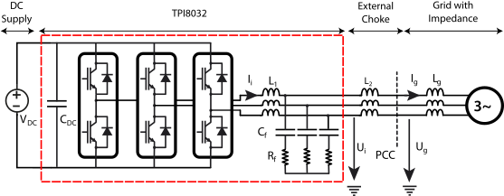
This technical note introduces a possible method of damping the LCL filter widely used in the grid-connected VSC application. The considered configuration is TPI8032 with an external choke forming an LCL filter connected to the grid, illustrated in Fig. 1.
Damping techniques in grid-connected converters
Passive damping techniques use additional passive elements in series or parallel with L or C to dampen the resonance [1]. They are simple to implement, low-cost, and have less design effort. The drawback is the reduction in the overall system efficiency due to the power losses and weakening of the high-frequency harmonic attenuation behavior of the filter.
Active damping techniques use modifications in control algorithms to suppress resonance without additional power losses associated with passive damping techniques. However, they often increase system complexity, design effort, and may require additional sensors. Active damping can be achieved either by cascading a digital filter with the current controller or by feeding back the state variables [4].
Active damping methods are generally preferred over passive damping due to the absence of additional power losses. However, for active damping, precise tuning of controller parameters is essential to ensure system stability, as improper settings can degrade performance. Digital control delays, including computation and PWM delays, can also affect stability and may lead to nonminimum-phase behavior unless carefully addressed [4].
Hybrid damping effectively addresses resonance problems in filter-based systems by integrating both passive damping and active damping techniques [3]. This approach aims to strike a balance between simplicity, which is a characteristic of passive damping, and enhancing damping robustness, a primary advantage of active damping. Hybrid techniques are known for significantly improving damping robustness, especially when confronted with wide variations in grid impedance.
Consequently, they are often recommended as a primary choice for applications such as single-phase or low-power three-phase grid-connected converters. However, the implementation of hybrid damping methods inherently involves a trade-off, as they introduce some power losses due to passive components and can increase the overall complexity and cost of the filter system compared to simpler, purely passive solutions. One example of a hybrid damping method is the combination of an RC damper with a digital notch filter [3]. A comparison of different damping methods is presented in Table I.
| Damping Method | Advantages | Drawbacks |
|---|---|---|
| Passive damping | – Easy to implement – Low design effort | – Increased power losses – Degraded attenuation performance of the filter |
| Active damping | – Increased control bandwidth – No power losses – Effective for suppressing high-frequency harmonics | – Increased design effort for active damper tuning – Effectiveness can be reduced by system parameter variations – May require additional sensors |
| Hybrid damping | – Improved damping robustness compared to passive damping – Low power losses compared to passive damping | – May require additional measurements – Increased overall complexity of circuit topologies and parameter design |
Different types of active damping methods
Feedback-based active damping methods are further classified into single-loop and multi-loop active damping. Single-loop active damping, such as notch, low-pass, or lead-lag filters, integrates a digital filter into the current loop without extra sensors, making it cost-effective and simple, but sensitive to LCL parameter variations and limiting bandwidth. Multi-loop active damping improves robustness and bandwidth by feeding back additional states (e.g., capacitor current, capacitor voltage, or weighted average current), creating virtual impedance to suppress resonance. However, this often requires extra sensors or estimation, adding cost and complexity.
A notable variant is the grid current feedback-based active damping with a high-pass filter. This only requires the grid current sensor and provides good bandwidth and robustness. However, it struggles under non-ideal point of common coupling conditions and faces trade-offs between high robustness and bandwidth.
Grid current feedback can be employed for current regulation and active damping. For the grid current feedback control scheme to be stable without any active damping, the LCL resonance frequency must be greater than the critical frequency (one-sixth of the system sampling frequency (\(f_s/6\))) [5]. Digital time delays or transport delays in the control loop inherently introduce damping, which can be sufficient to stabilize the system without additional damping measures. If the LCL resonant frequency is less than the critical frequency, an active damping loop is required to actively suppress the resonant dynamics. Even when the system parameters do not strictly demand active damping, such a loop can further enhance stability and increase the overall control bandwidth[4].
This technical note is focused on the single-loop grid current feedback method for active damping of the LCL filter. This method is selected because it doesn’t require extra sensors, and the only modification needed is within the control algorithm. The current controller can be implemented using two common approaches: either in the dq-domain or in the alpha-beta domain.
Implementation of the active damping
The LCL filter is a third-order filter widely adopted in grid-connected VSCs due to its superior harmonic attenuation performance and reduced size compared to L and LC filters. However, its inherent drawback is the presence of a resonance peak in its frequency response. Since the grid is assumed to be an ideal voltage source, the transfer function of the LCL filter is
$$\displaystyle\frac{i_{g}(s)}{U_{i}(s)}\bigg|_{U_g(s)=0}=\displaystyle\frac{1}{(L_1L_2C_f)s^3+(L_1+L_2)s} $$
In this example (L1 = 0.95mH, L2 = 0.65 mH, Cf =8.2µF), the cutoff frequency is 2.77 kHz. At this resonance frequency, the filter’s impedance theoretically approaches zero, which can lead to excessively high currents and significant output current distortion and oscillation. In practice, as the grid voltage source isn’t ideal (grid impedance is finite) and the cables and inductors have parasitic resistances, the current may still be high enough to damage the system. Consequently, damping methods primarily aim to introduce an effective resistance or modify the system’s dynamic response to suppress the resonance peak and stabilize the converter’s operation.
Feedback control strategies are commonly employed to modify the system transfer function by utilizing measurements such as inverter current, capacitor voltage, or grid current. In particular, the feedback of the grid current is interesting, as it enables the closed-loop transfer function to be reformulated in a manner equivalent to that of an LCL filter incorporating a damping resistor in parallel to the grid-side inductor of the LCL filter. This equivalence provides a clear and systematic interpretation of the underlying damping dynamics. The control of the LCL filter can be subdivided into two parts:
- A current controller implemented in the stationary reference frame (Fig. 2) or dq-reference frame (Fig. 3).
- The active damping which is always implemented in the stationary reference frame using grid-current feedback.
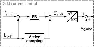
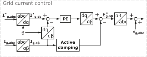
Grid current control
The grid current can be regulated using either vector control (PI) or the proportional resonant control (PR) method. The performance, tuning, and implementation of the PI controller are detailed in the technical note TN105. The implementation using the PR control will be discussed further.
The transfer function of the PR controller developed for regulating the grid current is given by the following equation:
$$G_{I\alpha\beta}(s)=k_p+k_r\displaystyle\frac{s}{s^2+\omega_{grid}^2}$$
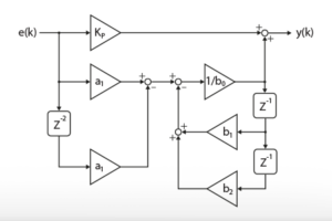
The discretization using the Tustin transformation with sample time Ts results in:
$$G_{I\alpha\beta}(z)= k_p+k_r \displaystyle\frac{\sin(\omega_{grid}T_s)}{2\omega_{grid}} \displaystyle\frac{1-z^{-2}}{1-2z^{-1}\sin(\omega_{grid}T_s)+z^{-2}}$$
Active damping loop
The active damping is added using a feedback loop on the grid current. The three equivalent circuits in Fig. 4 are obtained through a systematic impedance-based analysis that generalizes the physical circuit property of grid current feedback active damping. The grayed components are virtually added in parallel to L2 due to the active damping loop, which is illustrated by a parallel block named “active damping” shown in Fig. 2 and Fig. 3 and is represented by \(G_{AD}(s)\) in Fig. 4.
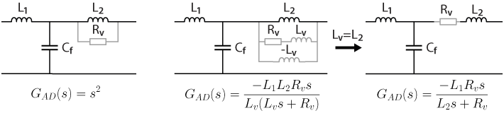
A feedback with the active damping loop transfer function s2 enables inserting a virtual resistor in parallel with the inductor L2, as shown in Fig. 4 (left). However, the implementation of a double derivative is problematic because of the noise amplification and the requirement of high sampling rates. Alternatively, a transfer function can be used as follows:
$$G_{AD}(s)=-\displaystyle\frac{L_1L_2R_vs}{L_v(L_vs+R_v)}$$
corresponding to the circuit in Fig. 4 (middle). It depicts a series RL damper in parallel with an additional negative virtual inductance −Lv. The negative virtual inductance is particularly beneficial as it helps to mitigate the phase lag caused by time delays in a digitally controlled system, thereby shrinking the region of nonminimum-phase behavior. This feature is critical for system stability and robustness.
If the added virtual inductor is chosen equal to the grid-side inductor L2 (Lv =L2), the added grid-side part (L2, Lv, Rv) is virtually replaced by a virtual resistor Rv in series with the grid-side inductor L2, as shown in Fig. 4 (right). As the transfer function of the active damping loop resembles that of a high-pass filter, it can also be written as
$$G_{AD}(s)=-\displaystyle\frac{L_1R_vs}{L_2s+R_v}=-\displaystyle\frac{k_{ad}s}{s+\omega_{ad}}$$
where \(\omega_{ad}\) and \(k_{ad}\), are the cutoff frequency and gain of the high-pass filter, respectively.
The discretization using the Tustin transformation with sample time Ts leads to the following equation, which is directly implementable in Simulink:
$$G_{AD}(z)=\displaystyle\frac{-2k_{ad}\left(z^{-1}-1\right)}{\left(\omega_{ad}T_s+2\right)+\left(\omega_{ad}T_s-2\right)z^{-1}}$$
Tuning of the active damper
The conventional approach is to tune the grid current controller and active damper independently. An active damper is recommended to be co-designed together with the grid current controller using root locus or any other analytical technique because their parameters, such as \(k_{ad}\), \(\omega_{ad}\), \(k_p\), and \(\omega_c\), directly influence each other. Here are some important tips to tune the active damper:
- The critical frequency \(\omega_{v}\) is the frequency above which Re{\(Z_{v}\)} (where \(Z_{v}\) is the virtual impedance) becomes negative and hence causes a non-minimum phase characteristic of the system, which must be avoided.
- High values of \(\omega_{ad}\) will result in higher \(\omega_{v}\).
- If \(\omega_{res}\) (angular resonance frequency) is high, \(\omega_{v}\) must also be set high for the active damper, such that \(\omega_{res} < \omega_v\) for the active damper to work correctly.
- Small (\(\omega_{res}\)) of the LCL filters do not demand a high \(\omega_{ad}\).
- The active damper should be designed with low values of \(\omega_{ad}\) since \(\omega_{v}\) is also relatively low. Otherwise, it will result in a more oscillatory transient response.
- If \(\omega_{res}\) > \(\omega_s/6\) (where \(\omega_s\) is the angular sampling frequency), the active damping is not needed to stabilize the grid-current feedback VSC. However, it still improves the control dynamics.
- The active damper gain \(k_{ad}\) should not be increased excessively, as it causes the root loci to move out of the unit circle in the z-domain, making the system unstable.
Software resources
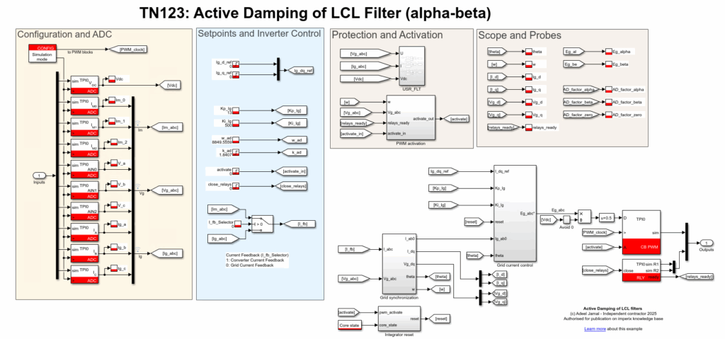
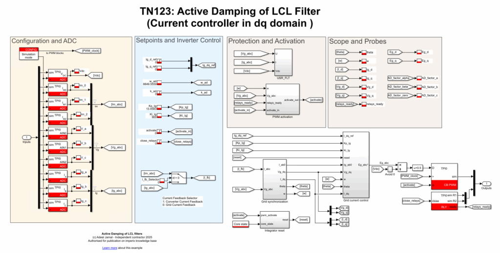
The file TN123_ActiveDamping_ab0_Simulink.zip and the file TN123_ActiveDamping_dq0_Simulink.zip contain the simulation/code generation files for the implementation of the current controller and active damper in the alpha-beta domain and for the implementation of the current controller in the dq domain in Matlab, respectively. The overall structure of the controller, in addition to ADC and PWM blocks, can be seen in Fig. 5 and Fig. 6.
Simulation results
The system and the control presented in this note are simulated using Simulink. The system and control parameters are summarized in Table 2. An external inductor L2 is added after the TPI8032 to enable an LCL filter configuration. For the sake of brevity, only the results of the PR control are presented next.
| Parameters | Value | Parameters | Value |
|---|---|---|---|
| Grid voltage (line-to-line) | 400 VRMS | Grid frequency | 50Hz |
| Inverter side inductor L1 | 0.95mH | Grid side inductor L2 | 0.65mH |
| Capacitor Cf | 8.2µF | L2 coil resistance Rf2 | 100mΩ |
| Grid inductor Lg | 10µH | L1 coil resistance Rf1 | 54mΩ |
| Equivalent capacitor resistance (Rf) | 10Ω | DC link capacitor (CDC ) | 1.5 mF |
| Control/switching frequency \(f_s\) | 50kHz | DC bus voltage VDC | 700V |
| Proportional gain (PR controller) kp | 5V/A | Resonant gain (PR controller) kr | 500Vs/A |
| Active damping gain kAD | 1.84 | Active damping pulsation ωAD | 18850 rad/s |
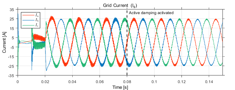
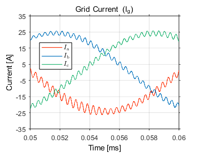
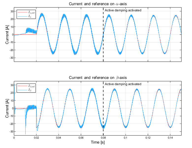
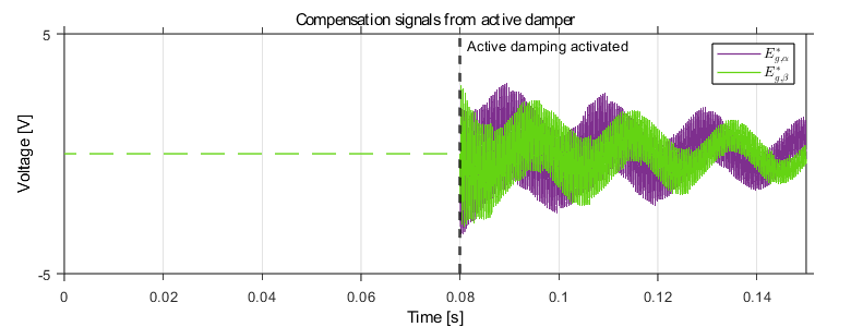
Fig. 7-10 shows the grid currents in the abc domain, \(\alpha \beta\) domain, and the compensation signal produced by the active damper. The converter’s control is first synchronized to the grid, and at t = 0.01s, the main TPI relay is closed. Sinsoidal references with peak current value of 25 A are applied at t = 0.02s for the \(\alpha\)-component, and the \(\beta\)-component with a 90° phase lag. The result of the activation of the active damping at 0.08s can be clearly seen; the active damping loop is able to suppress the resonance frequency and dampen the ripple. The compensation signals generated from the active damper can be seen in Fig. 10. Before the active damping gets activated, the ripple frequency seen in the grid current is around 2.63 kHz which corresponds to the resonance frequency of the LCL filter (\(f_\mathrm{res}\) = 2.77 kHz) as shown in Fig. 8. If the current exceeds the maximum current rating, the built-in over-current protection mechanism in TPI8032 would block the generation of inverter PWM signals, therefore blocking the grid currents.
The following figures show the system response to the sinusoidal reference current in \(\alpha\beta\) domain, with the active damping loop properly configured.
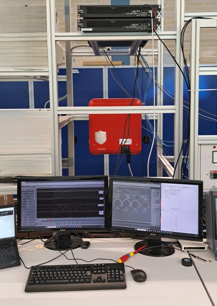
Experimental setup
The TPI8032 is connected via an external choke L2 to the grid. A programmable DC power supply is used to power the DC link. Three external voltage sensors are placed at the PCC to measure the grid voltage. The following list describes the required hardware and software. It comprises imperix products as well as additional components commonly available in power electronic research laboratories:
- Imperix products
- 1x TPI8032 (Three-phase fully programmable inverter)
- Control development tools for Simulink and PLECS (ACG SDK), with a valid license
- Cockpit to monitor and debug
- Additional software
- Additional hardware
- 3x inductor/chokes (0.650 mH)
- 3x DIN voltage sensors
- Programmable DC power supply
- Safety laboratory cables (banana)
Note that if the inductor value is different, the controller and active damper gain have to be tuned accordingly. For more information on how to get started with TPI8032, please refer: PN190: Getting started with the TPI 8032
Experimental results
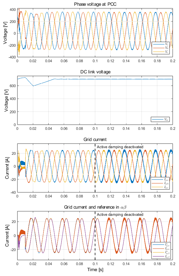
The TPI 8032’s DC link is pre-charged using TPI relay, as it ensures safe charging current levels. The DC power supply voltage of 700V is then turned on before capturing the results using imperix cockpit. For further details, refer to the getting started guide for preparing the TPI8032 for the experiment. Experimental result related to the active damping in the alpha-beta domain is shown in Fig. 11. At t = 1 ms, PWM is enabled, and it can be seen that the controller works to maintain the current at zero. At t = 10ms, the d-component current reference setpoint of 25A is applied, and the q-component current reference setpoint is always maintained at zero. In PR controller implementation, d and q component reference signals are transformed to \(\alpha\beta\) equivalent using the PLL’s angle output. At t = 100ms, active damping is deactivated, which results in the oscillations in the output current signals, and this can be directly related to the resonance frequency of the LCL filter.
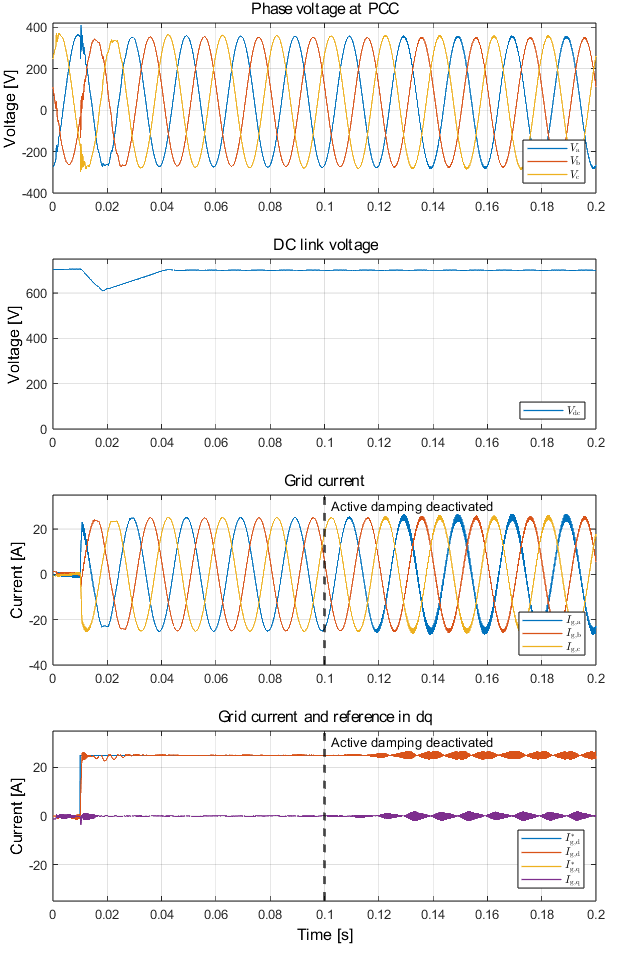
Similarly, experimental results related to the active damping method with current control implemented in the dq domain are shown in Fig. 12.
Conclusion
This technical note demonstrates the effective application of active damping to address the inherent resonance issues of LCL filters in grid-connected VSCs. It has been notably shown that:
The implementation, validated through both simulation and experimental results using the imperix TPI8032 platform, proves that this method significantly enhances system stability and improves the quality of the grid current by actively suppressing the LCL filter resonance frequency.
To go further from here…
Other application examples where active damping has been used can be found in: AN005: Back-to-back three-phase converter with grid-tied LCL filter
TPI8032 can also be used to program any controller for grid-connected converters. More examples of the TPI8032 are available in the knowledge base for various applications, such as:
TN163: Active power filters for harmonics mitigation
TN167: Grid-following Converter
References
[1] R. N. Beres, X. Wang, M. Liserre, F. Blaabjerg, and C. L. Bak, “A Review of Passive Power Filters for Three-Phase Grid-Connected Voltage-Source Converters,” in IEEE J. of Emerg. Sel. Topics in Power Electron., Vol. 4, 2015.
[2] J. Dannehl, F. W. Fuchs, S. Hansen, P. B. Thogersen, “Investigation of Active Damping Approaches for PI-Based Current Control of Grid-Connected Pulse Width Modulation Converters With LCL Filters” in IEEE Trans. on Industry Applications, Vol. 46, August 2010.
[3] W. Wu, Y. Liu, Y. He, H. S.-H. Chung, M. Liserre, and F. Blaabjerg, “Damping Methods for Resonances Caused by LCL-Filter-Based Current-Controlled Grid-Tied Power Inverters: An Overview,” in IEEE Trans. on Ind. Electron., vol. 64, 2017.
[4] X. Wang, F. Blaabjerg, P. C. Loh, “Grid-Current-Feedback Active Damping for LCL Resonance in Grid-Connected Voltage-Source Converters”, in IEEE Trans. on Power Electr., vol. 31, January 2010.
[5] Z. Xin, X. Wang, P. C. Loh, and F. Blaabjerg, “Grid-Current-Feedback Control for LCL-Filtered Grid Converters With Enhanced Stability,” in IEEE Trans. on Power Electron., vol. 32, 2016.