Table of Contents
The CSR block of the imperix Power library models a current measurement in Simulink and PLECS. It reproduces the measurement bandwidth of the selected imperix sensor, so that a simulated control loop sees the same measurement dynamics as the hardware.
The block supports the CSR-40-HBW high-bandwidth current sensor and the CSR-25-LNO low-noise current sensor (formerly CSR-25-HBW). It also supports the previous-generation DIN50A.
Measurement chain and modeled effects
On real hardware, a current measurement passes through three stages. The sensor converts the measured current into a low-voltage signal. An RJ45 cable carries the analog signal to the controller input, where it is sampled. In the control model, the ADC block converts the sampled value back into amperes using the selected sensor’s sensitivity.
In simulation, the current measurement block represents the first stage. It is inserted in series in the branch whose current is measured and outputs that current, filtered by the measurement bandwidth of the selected sensor. Sampling and quantization are modeled by the ADC block.
The current measurement block does not model noise, offset, sensitivity error, saturation beyond the measurement range, or rejection of switching-node voltage transients.
Measurement bandwidth and modeling levels
The current measurement block represents a sensor either as an ideal measurement or as an ideal measurement followed by a first-order low-pass filter (LPF). The time constant of the LPF follows from the measurement bandwidth:
$$(1) \quad \quad \tau = \frac{1}{2\pi f_{BW}}, \qquad H(s) = \frac{1}{1 + s\tau}$$
where \(f_{BW}\) is the bandwidth in Hz and \(\tau\) the time constant in s.
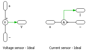
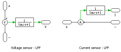
As for all imperix products, two modeling levels are available: (A) Simple and (B) Detailed. However, for current sensors, all products are modeled as ideal devices anyway, because their bandwidth exceeds the limits of both the Simple and Detailed modeling levels (4kHz and 100kHz, respectively).
| Sensor | Bandwidth setting | (A) Simple | (B) Detailed |
|---|---|---|---|
| CSR-40-HBW | 3 MHz | Ideal | Ideal |
| CSR-40-HBW | 300 kHz | Ideal | Ideal |
| CSR-25-LNO | 1.5 MHz | Ideal | Ideal |
| CSR-25-LNO | 150 kHz | Ideal | Ideal |
| DIN50A | 200 kHz | Ideal | Ideal |
Simulink block
Port specification
- The two electrical ports connect the block in series with the branch whose current is measured.
- The output
iis the measured current through the two electrical ports, in amperes.


Parameters
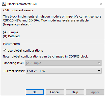
- Use global configurations: when ticked, the block takes its modeling level from the CONFIG block, so that one setting applies to all blocks of the model. Untick it to give this block its own modeling level, for instance, the Detailed level for one slow measurement only.
- Modeling level: for now, irrelevant: Both Simple and Detailed levels model every sensor as ideal.
- Current sensor: selects the modeled sensor. Select the sensor installed on the hardware.
PLECS block
Port specification
- The two electrical ports connect the block in series with the branch whose current is measured.
- The output
iis the measured current through the two electrical ports, in amperes.

Parameters
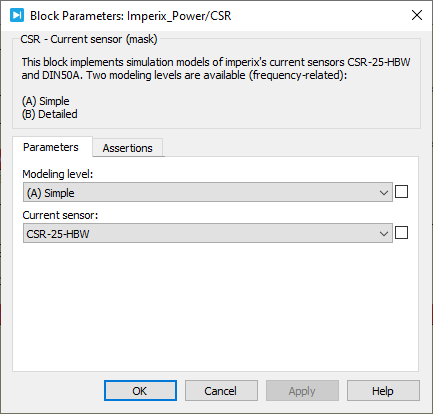
- Modeling level: for now, irrelevant: Both Simple and Detailed levels model every sensor as ideal.
- Current sensor: selects the modeled sensor. Select the sensor installed on the hardware.
Probe signals
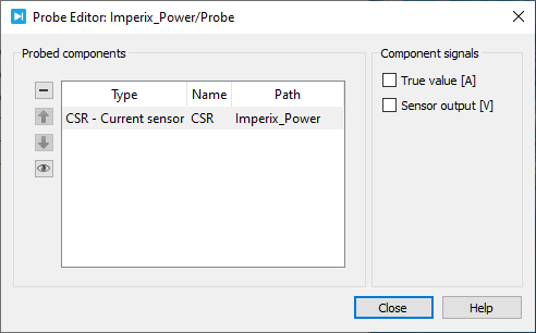
The following signals can be monitored by a Probe block in PLECS.
- True value [A]: the actual current through the two electrical ports, in amperes.
- Sensor output [V]: the voltage delivered by the modeled sensor, in volts.
 By Shu Wang • May 7, 2024 • PN150