Table of Contents
This page presents a practical example of Aurora communication with Plexim simulators, namely the RT-Box 1, RT-Box 2 and RT-Box 3. It provides a ready-to-use user application, along with an FPGA design specifically configured for interfacing Plexim simulators.
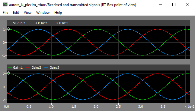
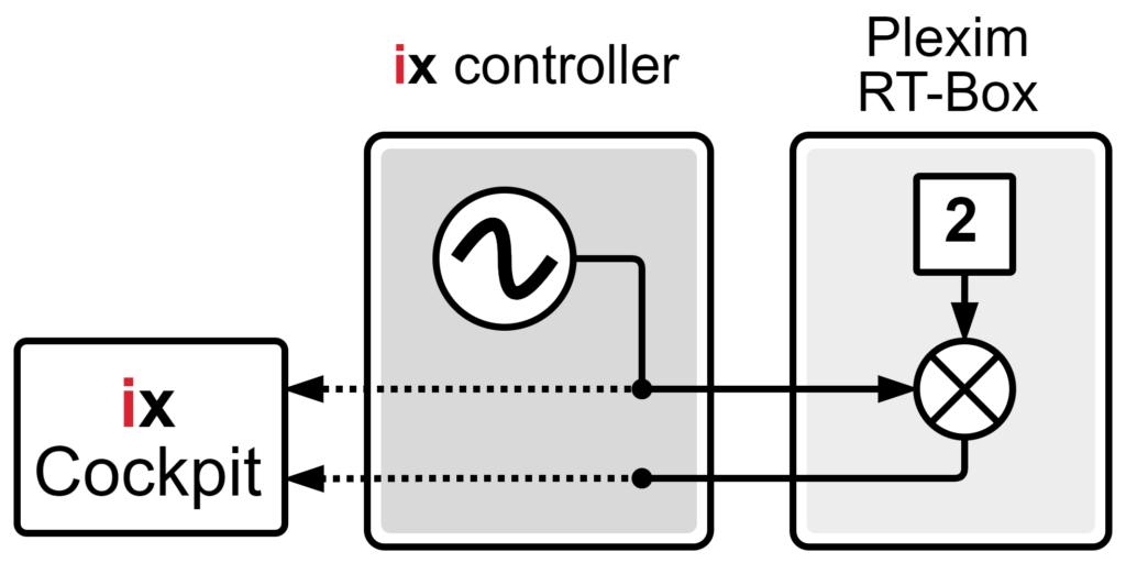
To demonstrate the setup, this page also includes a fully functional PLECS model for the RT-Box simulator implementing a simple loopback example. In this example, a three-phase sine wave is transmitted from the imperix controller, multiplied by two in the simulator, and sent back to the controller.
For broader technical background, a general introduction to SFP communication with third-party devices is available. That page covers fundamental SFP considerations, describes the full communication chain, and provides guidance on implementing the imperix-side drivers.
Case study
This case study demonstrates a straightforward signal processing loop:
- The controller generates a three-phase sine wave and transmits it to the RT-Box via SFP.
- Upon receipt, the RT-Box applies a gain of two to the three signals – doubling the amplitude of the sine wave – and returns them to the controller, also via SFP.
- Finally, the original transmitted values and the received return signals are compared in real-time in Cockpit, showing the proper operation of the system.
Required software
- Vivado Design Suite (version 2022.1 is recommended)
The Xilinx installation page details the installation procedure. - FPGA sandbox template 3.10 or later.
Available on the FPGA download page. - C++ or ACG SDK version 2024.3 or later.
Available on the SDK download page.
This project has been tested with a Plexim RT-Box 1 and PLECS 4.5.9.
Downloads
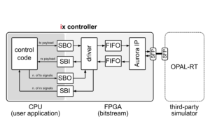
As explained in the setup overview, the SFP communication requires the three following software parts:
- The user application, running in the imperix controller’s CPU and provided as a Simulink or PLECS script.
- The FPGA bitstream, loaded in the imperix controller’s FPGA and provided as generation scripts.
- The RT-Box application, provided as a PLECS model.
| User application | FPGA bitstream | RT-Box application |
| aurora_ix_template.slx aurora_ix_template.plecs | aurora_ix_plexim_gen_scripts.zip | aurora_ix_plexim_rtbox.plecs |
RT-Box application
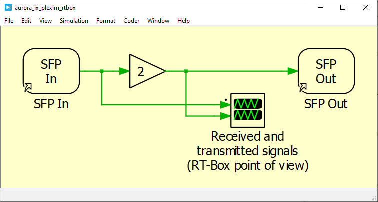
The application running in the RT-Box simply reads the values from the imperix controller, multiplies them by a gain of 2, and sends them back to the imperix controller. A scope is added to enable the real-time control of the setup via the External Mode of the RT-Box.
The SFP In block is configured to read 3 signals from the SFP A port of the RT-Box. The SFP Out block is also configured on SFP A.
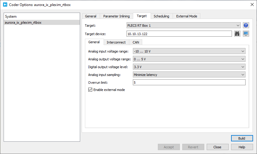
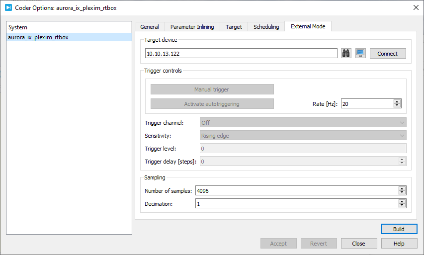
To build and load the model on the RT-Box, press Ctrl+Alt+B to open the Coder Options menu. In the Target tab, configure the target type and IP, and enable the External Mode via the checkbox. Then, navigate to the External Mode tab and press Build.
To launch the acquisition using the External Mode of the RT-Box, wait for the code to be built and loaded, then press Connect and Activate autotriggering.
The code should now be running in the RT-Box and the scope acquisition started (showing only zeroes if the imperix controller is not yet configured).
Communication chain
Overview
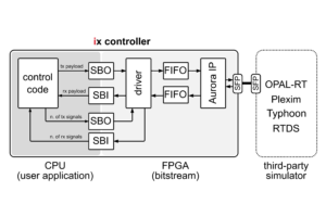
The overview of the communication chain is presented in the setup overview. However, for Plexim, the logic is slightly different: a proprietary IP is added in the design, between the FIFOs and the Aurora IP. This IP implements an additional layer of encapsulation to comply with the frame structure expected by the RT-Box.
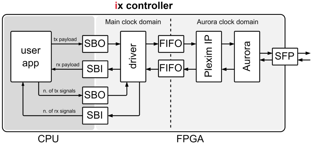
rtbox_aurora_adapter in Vivado.The main clock domain always runs at 250 MHz, while the frequency of the Aurora clock domain varies with the configuration of the Aurora IP. In this example, the frequency is 97.656 MHz with the configuration presented in the Aurora parameters section.
Vivado project
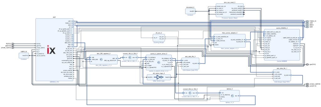
The Vivado project is provided in the form of generation scripts. As explained in the PN109 , the scripts automatically create and open the project illustrated below. The bitstream can be directly generated by simply pressing Generate Bitstream in the left navigation bar in the Vivado environment.
As provided in the source files, the driver supports the exchange of up to 50 signals in each direction and the Aurora communication is linked to the SFP 0 (UP) port of the imperix controller.
Once generated, the bitstream can be loaded onto the imperix controller using Cockpit. A reboot is required for the bitstream change to take effect.
Modules/IPs description
The Vivado project contains the following VHDL modules and IPs.
| Module name | Type | Description |
|---|---|---|
| sbio_256_registers | VHDL module | Instantiates and provides access to SBIO bus registers in the FPGA. More information is provided here. |
| convert_16b_to_32b | VHDL module | Converts the 16-bit words of the SBIO bus back into the 32-bit words of the payload. |
| sfp_aurora_rtbox_driver | VHDL module | Custom driver provided by imperix to communicate with the RT-Box from Plexim ; mainly acts as a parallel-to-serial transmitter and serial-to-parallel receiver. |
| convert_32b_to_16b | VHDL module | Converts the 32-bit words received from the RT-Box through the driver into 16-bit words compatible with the SBIO bus. |
| latcher | VHDL module | Ensures data coherency by preventing the update of the SBI registers while the CPU is reading. |
| AXI4-Stream Data FIFO | Vivado IP (Xilinx) | Handles the clock domain crossing between the main 250 MHz domain of the imperix firmware and the Aurora clock domain ; buffers the frame in the transmission direction. |
| rtbox_aurora_adapter | Vivado IP (Plexim GmbH) | Slightly truncates the transmitted and received frames to comply with the RT-Box requirements ; filters out the frames with an invalid CRC ; handles the synchronization mechanism when used (here, not used). |
| Processor System Reset | Vivado IP (Xilinx) | Handles reset signals to properly initialize the Aurora IP. |
| Aurora 64B66B | Vivado IP (Xilinx) | Handles the Aurora communication and interfaces with the underlying hardware logic. |
| Clocking Wizard | Vivado IP (Xilinx) | Handles the clock signals, providing the Aurora domain clock and adding proper buffers. |
| Utility Vector Logic | Vivado IP (Xilinx) | Converts the active-high reset signal from the sync_pulse into an active-low reset signal for the FIFOs. |
| Constant | Vivado IP (Xilinx) | Provides a constant high signal to annihilate unused active-low reset signals. |
Aurora parameters
The included Aurora IP comes with the correct configuration pre-applied for interfacing with Typhoon HIL simulators. When creating a project from scratch, the Aurora IP must be configured in Vivado with the specific parameters listed below.
| Protocol | Aurora 64B66B | Flow Control | None |
| Line Rate (Gbps) | 6.25 | Little Endian Support | No |
| Dataflow Mode | Duplex | CRC | Yes |
| Interface | Framing | DRP Mode | Disabled |
Plexim-specific notes
- Received frames with an invalid checksum are dropped by the Plexim IP. This behavior can be changed manually by double-clicking the rtbox_aurora_adapter Plexim IP in Vivado and unchecking the Drop packages with invalid checksum checkbox.
- An additional rx_CRC_check_ok signal is available at the output of the driver. This output is updated simultaneously with rx_vld and indicates if the frame has a valid CRC. If invalid frames are dropped by the Plexim IP (see previous item), the CRC_check_ok is expected to be always high.
Experimental validation
Physical setup
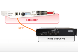
The physical setup is straightforward:
- Connect both devices to the network, so that they can be configured and monitored from the PC.
- Connect the imperix controller to the RT-Box with an SFP cable. As provided, this example considers the port SFP 0 (UP) on the controller and SFP A on the RT-Box.
- Turn on the two devices.
Software-side setup
To experimentally validate the system:
- Download the three software parts available in the downloads section.
- Build and load the RT-Box application on the RT-Box.
- Generate the bitstream for the imperix controller.
- Load the bitstream on the imperix controller via Cockpit.
- Build the user application template and launch it on the imperix controller via Cockpit.
- Use Cockpit to monitor the exchanged signals.
The whole system should now be running.
Real-time monitoring
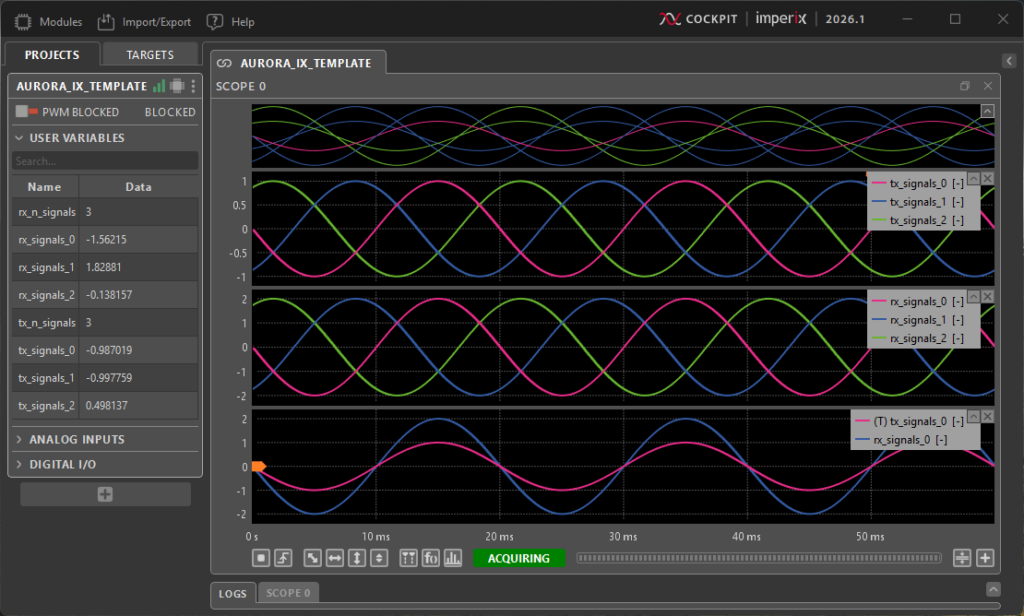
Connect to the imperix controller with Cockpit. Add a scope in the project (from the Modules tab in the top bar) and drag-and-drop the variables of interest.
The exchanged signals can now be monitored in real-time in Cockpit. As expected, the amplitude of the transmitted signals is multiplied by two in the RT-Box.
The exchanged signals can also be monitored from the RT-Box, using the External Mode, as described in the RT-Box application section.