Table of Contents
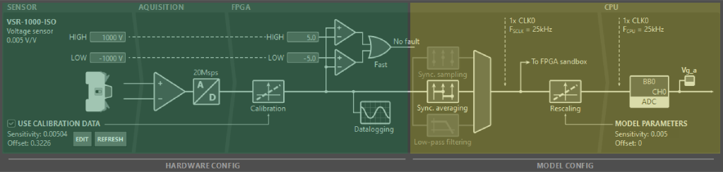
A total of 24 analog channels are available on the B-Box 4, all of which can be configured as either inputs or outputs. From the user’s perspective, each of these channels is actually a chain of hardware parts and fast software routines, which make the data available to the user’s control algorithm:
- The hardware section (in green below) consists of a sensor, external to the B-Box 4, connected to the analog I/O. Inside the B-Box 4, the input signal is captured by an analog-to-digital converter (ADC). The data is then fed through the FPGA to the hardware protection and datalogging, as well as forwarded for further processing, ultimately reaching the model/software section.
- In the model section (in yellow below) – sometimes also referred to as software section – the FPGA continues processing the data by sampling it down to the CPU clock rate, rescaling it to a meaningful quantity (based on the sensitivity of the whole chain), and transferring it to the CPU memory in the shortest time possible.
These two parts correspond to two distinct groups of settings, which can be configured in different ways:
- Hardware settings can be configured either through Cockpit or directly using the B-Box 4’s front panel. These settings are stored inside the controller itself (on the SSD) and are thus applied irrespectively of the project that is loaded onto the device.
- Model settings are configured exclusively from the control code. These settings are therefore saved in the Simulink/PLECS/C++ files, independently of the target hardware.
Hardware settings
In B-Box 4, hardware settings are limited to two types of parameters:
- Hardware protection settings, including the safety limits (high and low) and the reaction time.
- Sensor calibration options for compatible imperix devices.
These settings are described below. Documentation about similar resources in other imperix controllers can be found in PN108.
Hardware protection (safety limits) settings
The B-Box 4 offers user-configurable protections for each channel, including:
- The limit high threshold, triggered if the measured value is above the threshold.
- The limit low threshold, triggered if the measured value is below the threshold.
- The reaction time, defining how quickly the B-Box 4 is expected to react after a threshold is exceeded:
- Ultra fast, equating to 4 samples or a total delay of at most \(0.8\mu s\)
- Fast, equating to 20 samples, or a total delay of at most \(1.6\mu s\)
Advice on how to choose safety limit thresholds is provided in PN257.
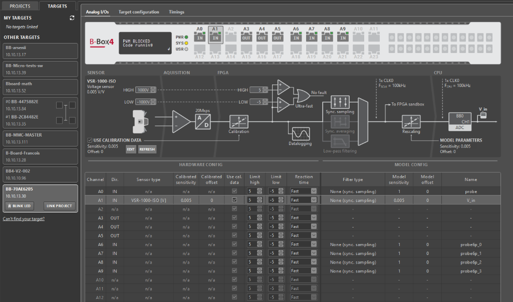
Safety limit protection trip
In case a limit is exceeded, a protection trip is declared, immediately leading to the following actions:
- All PWM outputs are immediately blocked.
- The core state machine of the B-Box 4 is changed to the FAULT state.
- The orange LED of the corresponding RJ45 socket port lights up, indicating the origin of the trip.
- Cockpit also indicates the origin of the fault.
As explained in PNxxx, the controller remains in FAULT state until the protection trip is acknowledged, which is only possible once the conditions that created the fault are removed. It is highly recommended to clearly identify and understand why the trip happened before acknowledging it. With the B-Box 4, acknowledging a protection trip can be done:
- In Cockpit, by clicking the ACKNOWLEDGE button appearing in the target information (left bar).
- Using the front panel, selecting ACKNOWLEDGE and confirming the action (YES/no) afterward.
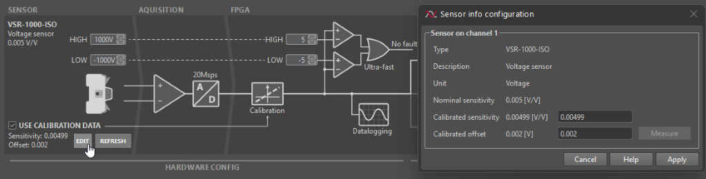
Sensor calibration settings
With the B-Box 4, recent imperix devices can be automatically recognized, facilitating the detection of possible configuration errors. This is achieved using a 1-wire communication link embedded inside the RJ45 cables, which supports exchanges between the B-Box 4 and compatible sensors. The same link also enables leveraging factory calibration data – pre-written inside the sensors during product testing – so as to deliver superior precision without any user action. From a hardware configuration perspective, only one setting is involved:
- Use calibration data – toggles using (or not) the calibration data provided by the sensor.
Information on how to leverage auto-identifcation and edit calibration setting is given in PN255.
How to edit hardware settings
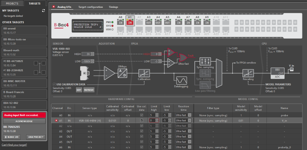
To access and edit hardware settings of the B-Box 4 from Cockpit:
- Navigate over to the Cockpit Targets perspective by clicking on the TARGETS button in the left bar.
- From the left bar, choose the relevant device and select the Analog I/Os tab in the central area.
- Read/modify the configuration of a given channel by selecting it in the virtual representation of the B-Box 4 front panel or in the table in the bottom half of the display.
The same settings are also available via the LCD screen and rotary push button. To access this information:
- Press the button, select the “Analog I/O” menu and enter it by pressing the button again.
- Select the desired input channel and enter its menu.
- Select one of the options, rotate the button to change its value and enter again to confirm the changes.

Model settings
In B-Box 4, model (software) settings involve multiple parameters:
- The channel direction (input or output).
- The desired down-sampling or filtering technique.
- The cut-off frequency of the low-pass filter (if active).
- Sensitivity and offset information about the connected sensor.
These settings are described below. Most of these settings are shared with other imperix controllers, as documented in PN108.
Channel direction
Channel direction is indirectly set by assigning an ADC resource (for input) or DAC resource (for output). It is indicated:
- In Cockpit’s target remote view (Analog I/Os tab of the corresponding B-Box 4).
- By the green LEDs next to each RJ45 socket. A steady light indicates the input mode, while a blinking state indicates the output mode.
Configuring the channel as an output activates the output amplifiers that drive its I/O pins. When operating as an input, these amplifiers are disabled, simply appearing as a very high-impedance in parallel to the input.
Filtering technique
Three configurations apply to the B-Box 4. These can be easily selected from the ADC block:
- Synchronous sampling works by taking the exact sample (from all the data points) that corresponds to the configured sampling phase (see CONFIG block). This approach results in the lowest possible sampling delay, at the cost of reduced robustness to noise and other possible measurement perturbations.
- Synchronous averaging is a technique that averages all points captured within one or two CLK0 periods, over an synchronous interval ending at the configured sampling phase (see CONFIG block). This results in excellent robustness to most sorts of possible perturbations at the cost of a slightly higher delay.
- Low-pass filtering is also possible, combined with down-sampling at the CPU rate. In the B-Box 4, this is implemented digitally. This offers a more aggressive attenuation in the high-frequency range. However, it also introduces a non-negligible group delay, which must be accounted for in the control algorithm.
These techniques are detailed and compared in the article Sampling techniques for power electronics. By default, using synchronous averaging is recommended.
Cut-off frequency
When low-pass filtering is used, the corresponding cut-off frequency can be selected (see ADC block). More information on the characteristics of the low-pass filter, can be found in the B-Box 4 datasheet. The available cut-off frequency settings are identical to the B-Box 3 (RCP).
Sensor sensitivity and offset
The analog-to-digital converters (ADCs) present in the B-Box 4 deliver 16-bit values, which are rescaled to usable 32-bit floating-point data prior to processing inside the CPU. To this end, information about the corresponding sensor’s sensitivity and offset is used.
For imperix sensors and power modules, this information can be easily configured by selecting the connected product from a pre-configured list (see ADC block).
How to edit model settings
The procedure for adjusting model settings is identical across all devices, due to their shared blockset. Comprehensive configuration instructions are provided in PN108.
Overview of all I/O configuration settings
The following table provides a complete overview of all front-end related configuration options, where they can be configured from and to which values:
| Parameter | Configurable from | Possible values | Comment |
|---|---|---|---|
| Calibrated sensor sensitivity | Cockpit Analog I/Os tab | Sensor-dependent | Values interpreted in [V/sensor unit] |
| Calibrated sensor offset | Cockpit Analog I/Os tab | Sensor-dependent | Values interpreted in [sensor unit] |
| Use sensor calibration data | Cockpit Analog I/Os tab | True, False | Only available with compatible products. |
| Safety limit high | Cockpit Analog I/Os tab and B-Box 4 front-panel | [-10V, 10V] or +inf | Accuracy ±1% m.v. ±10 mV |
| Safety limit low | Cockpit Analog I/Os tab and B-Box 4 front-panel | [-10V, 10V] or -inf | Accuracy ±1% m.v. ±10 mV |
| Protection reaction time | Cockpit Analog I/Os tab and B-Box 4 front-panel | Ultra fast, Fast | Max delay \(0.8\mu s\) and \(1.6\mu s\), respectively |
| Analog channel direction | The ADC and DAC block in the user code | In, Out | |
| Analog input acquisition mode | The ADC block in the user code | Sync. sampling, Sync. averaging | Sync. averaging can be set over 1 and 2 periods of CLK0 |
| Analog input Low-pass filter | The ADC block in the user code | Off, 0.5kHz, 1kHz, 1.6kHz, 2.5kHz, 4kHz, 6.4kHz, 8kHz, 10kHz, 16kHz, 20kHz, 32kHz, 40kHz, 64kHz, 80kHz, 100kHz | Always paired with Sync. sampling |