Table of Contents
This note introduces basic instructions in order to efficiently get started with the imperix ACG SDK on Simulink.
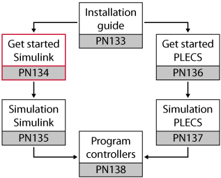
Related material
Suggested prerequisites
Suggested further readings
Default template
To start working with Simulink, different approaches are possible:
- Start from a personal (existing) Simulink model and add the imperix blocks to it.
- Start from an example found on the imperix knowledge base.
- Start from scratch using the default template.
The third approach is assumed here, in which case the corresponding steps are as follows:
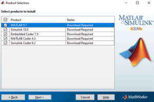
- Copy the base template into the folder of your choice (such as the workspace folder of Matlab). The base template is always located in: C:\imperix\BB3_ACG_SDK\simulink\user_template\imperix_template.slx
- The copied template can be renamed as long as the rules for Matlab/Simulink file naming are observed: the file must start with a letter and can be followed by letters, numbers or underscores.
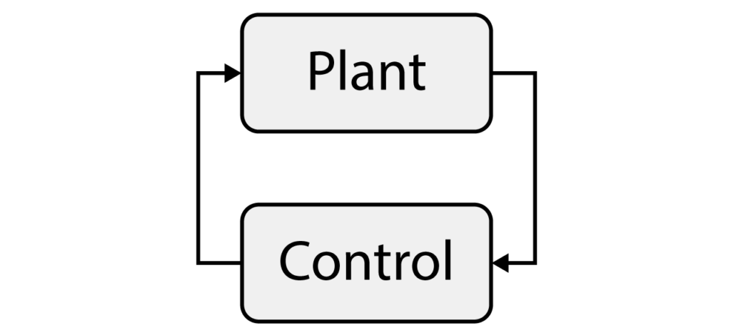
The default template (fig. below) contains a basic skeleton to start working right away. As for most imperix examples, the model contains two subsystems:
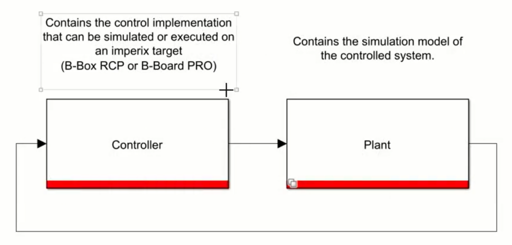
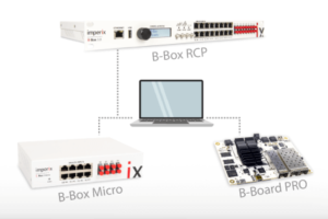
- Controller: contains the control implementation that can be simulated or used to generate the control code for the imperix controller (B-Box RCP, B-Box Micro, B-Board PRO, TPI8032). It also contains a configuration block that performs the main configuration of the Simulink model.
- Plant: contains the model of the system that is desired to be controlled. This is typically the model of the power system itself (e.g. converter, sources, grid, machine, sensors,…)
Plant subsystem
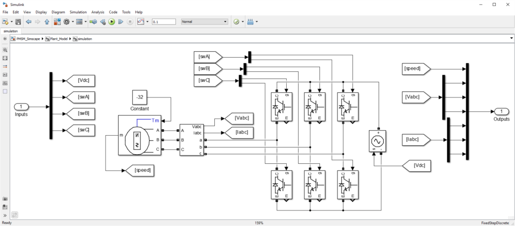
In order to run the control algorithm in simulation, Simulink needs a model of the real converter hardware (system to be controlled). This model should be located inside the Plant subsystem (see above). More information about using the Power library is available in PN150.
The plant model is only considered during offline simulation of the system. This means that, in code generation mode, the content of the plant model is ignored.
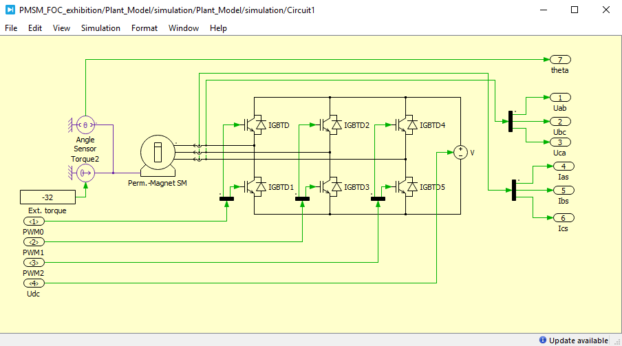
The figures below show two examples of plant models developed using Simscape Power Systems or PLECS blockset.
Control subsystem
Blockset library
Starting from the default template or an existing example, control implementation can be done using the blocks provided by the imperix ACG-SDK blockset, as well as any standard Simulink block.
The blockset can be found in the library browser (View > Library Browser [Ctrl+Shift+L]) and browsing to imperix ACG SDK.
Alternatively, the blockset can be accessed by selecting any imperix block in the base template and pressing Ctrl+L.
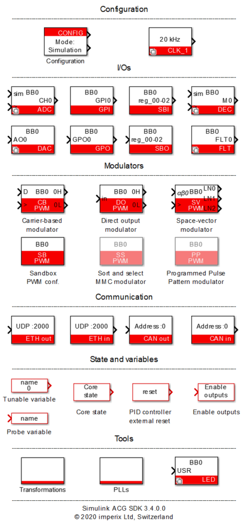
The imperix blockset is shown on the right. It essentially implements hardware-related mechanisms that are associated with analog and digital I/Os. The blockset also contains a few useful routines such as coordinate transformations, various types of PLLs, etc.
Basic control example
For the sake of example, a basic control algorithm for a buck converter is depicted below. It sets the output voltage to 12V, regardless of the measured input voltage.
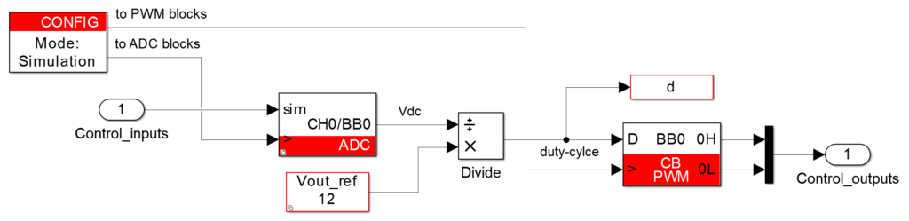
This basic control scheme contains:
- The Config block, which defines the main model parameters. This block is mandatrory.
- An ADC block to retrieve the simulated DC bus voltage in simulation, and the measurement of the corresponding real quantity in code generation: the voltage on the analog in put channel 0 of the first controller.
- A Tunable Parameter block to define a variable
Vout_refthat is accessible and modifiable in real-time from imperix Cockpit. - A Probe block to define a variable
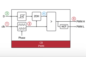
dthat can be logged in real-time using Cockpit. - A Carrier-based PWM (CB PWM) modulator to generate PWM signals with the duty-cycle d. The PWM signals are wired to the plant model in simulation and directly produced on the corresponding PWM outputs of the imperix controller in code generation (optical fibers).
The Config block provides two clock signals. This mechanism enables Simulink to accurately take into account the sampling instant during simulation, as well as the phase reference for phase-shifted carriers.
- An ADC clock signal that must be connected to the clock input of all ADC blocks.
- A PWM clock signal that must be connected to the clock input of all PWM blocks.
Simulation and code generation
Thanks to the ACG SDK, a unique Simulink model (i.e. a single file) can be used for both simulation (offline, on the computer) and code generation (i.e. the production of a binary executable, for use in real time on an imperix controller). The selection of the Model execution purpose can be made in the Config block:
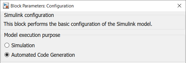
- In Simulation mode, the complete Simulink model is simulated, including both the Control and the Plant subsystems. Simulink uses the variable-step solver parameters specified in the Config block.
- In Automated Code Generation mode, C++ code is automatically generated by the Simulink Coder engine when the model is built (Ctrl+B). As the corresponding variant inside the Plant subsystem is disabled, no code is generated for this part. This is indeed the expected behavior, because the real plant is meant to be used instead of having its model simulated in the controller.
Simulation
Code generation
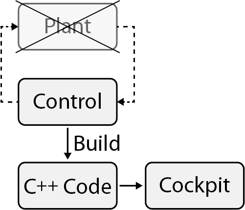
In code generation mode, once the code is generated and compiled, Cockpit opens automatically and loads the executable on the connected target controller. Information about how to interface and program imperix controllers is given in PN138.