
Table of Contents
The carrier-based PWM block supports generating PWM signals using common digital carriers. The following configuration options are available:
- The carrier shape can be selected from the following options: triangle, sawtooth, inverted triangle, or inverted sawtooth (see below).
- The carrier frequency can be configured by connecting the CB-PWM block to a CLK block. The frequency can even be configured and changed during control execution.
- The duty cycle and phase shift of the carrier can be adjusted independently during execution. These parameters can be updated either once or twice per period (with triangular-shaped carriers, see below).
- Like other PWM blocks, CB-PWM supports dead-time generation (see PWM).
- CB-PWM resources can be activated or deactivated during exection.
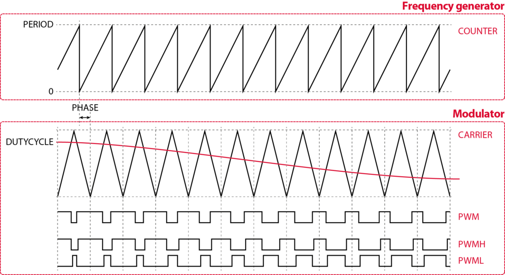
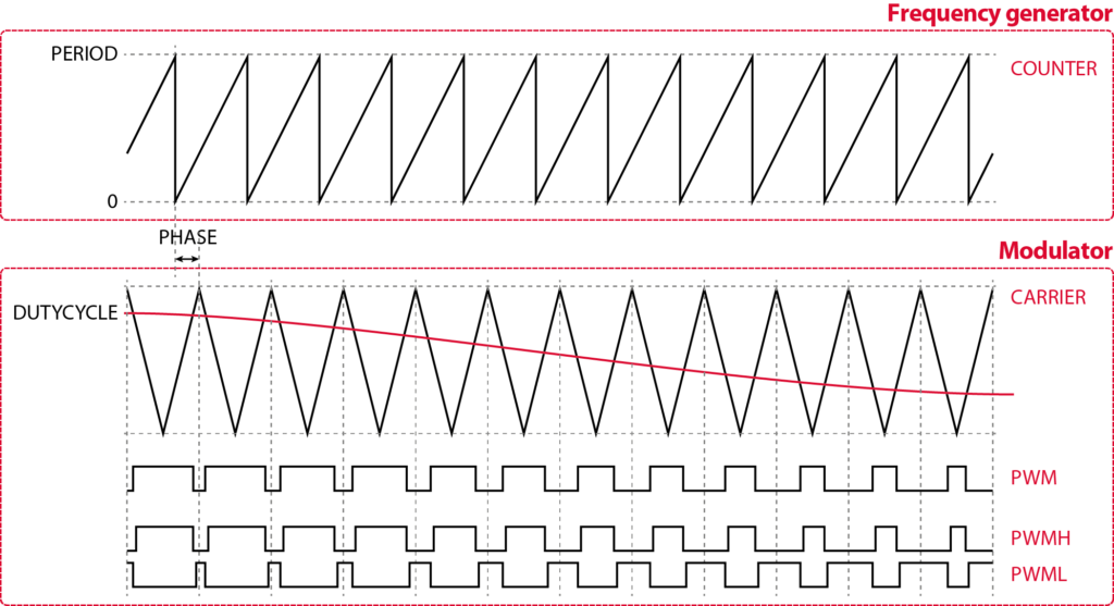
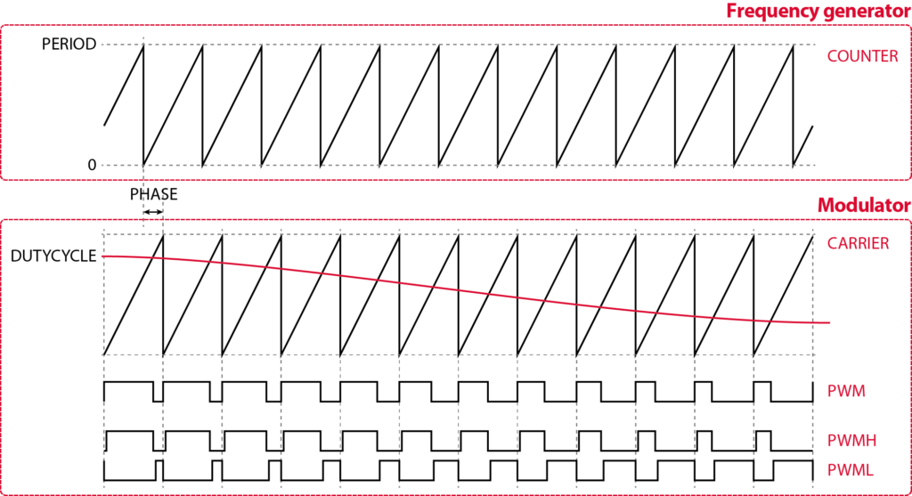
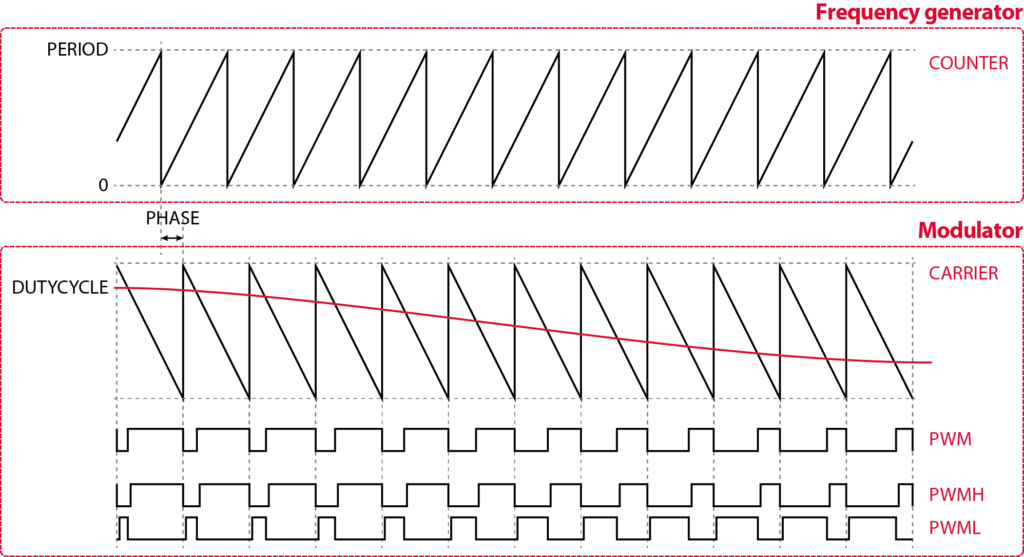
With sawtooth carriers, the duty-cycle and phase-shift parameters are always updated at the beginning of the PWM period. However, with triangular carrier shapes, two options are available:
- Using a single-rate update, these parameters are updated once per period: at the end.
- With a double-rate update, these parameters are updated twice per period: in the middle and at the end (i.e., when the carrier reaches its maximum and minimum).
Complete examples using single-rate and double-rate update are presented in PN259.
The time resolution of the CB-PWM resources is hardware-dependent:
- On Gen 3 devices (B-Box RCP, B-Box Micro, B-Board PRO and TPI8032) the CB-PWM resolution is directly set by the base clock of 250 MHz. This corresponds to a resolution of 4 ns at the signal edges.
- On the Gen 4 (B-Box 4), higher resolution is achieved using phase-shifted derivatives of the 250 MHz clock, effectively increasing it by a factor of 16.
| duty-cycle resolution (sawtooth) | duty-cycle resolution (triangle) | phase shift resolution | |
|---|---|---|---|
| High-resolution (B-Box 4 only) | 250 ps | 500 ps | 250 ps |
| Standard resolution (all other devices) | 4 ns | 8 ns | 4 ns |
High-resolution is automatically applied to the parameter (either duty cycle or phase) configured to be real-time tunable (set as a block input). If both are real-time tunable, the phase takes priority.
Parameters
The parameters output mode, addressed channel/lane, dead-time, and show ”activate” input can be configured the same way for all modulator types. These are documented on the PWM page.
Addressing
- Device ID selects which B-Box/B-Board to address when used in a multi-device configuration.
- Output mode selects between a single PWM signal and complementary signals with a dead-time.
- Addressed channel(s) or Addressed lane(s) (vectorizable) selects the PWM outputs to address.
Modulation
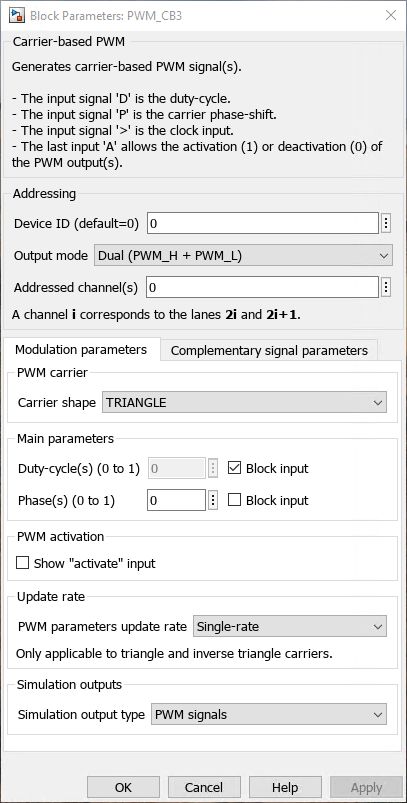
- Carrier type: selects the type of carrier (TRIANGLE, SAWTOOTH, INVTRIANGLE, or INVSAWTOOTH)
- Duty-cycle(s): (vectorizable) configures the duty cycle. It can be tuned in real time using the D signal input or configured only once via the block mask parameter.
- Phase(s): (vectorizable) configures the carrier phase-shift relative to the CLK. It can be tuned in real time using the P signal input or configured only once via the block mask parameter.
- Show ”activate” input: makes the A signal input visible. If not checked, the CB-PWM block is active by default.
- PWM parameters update rate: selects when the duty cycle and phase parameters are updated.
- Single-rate: they are applied at the end of the carrier period.
- Double-rate: they are applied twice per carrier period: when the carrier reaches its lowest point and when it reaches its highest point. (for TRIANGLE and INVTRIANGLE carriers only)
- Simulation output type:
- PWM signals: outputs are logic gate signals 0 or 1.
- Duty-cycle: outputs are duty-cycles between 0 and 1. This option is only relevant for simulation with period-averaged models.
Complementary signal parameters
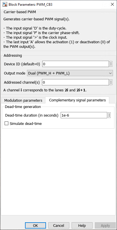
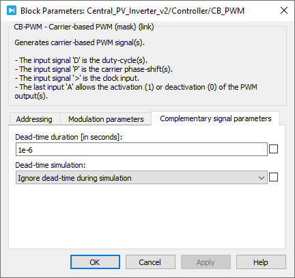
- Dead-time duration: configures the dead-time duration if the Output mode is set to Dual (PWM_H + PWM_L).
Simulink block
Signal specification
- The input signal
Dis the duty-cycle (0.0 to 1.0) - The input signal
Pis the carrier phase-shift relative to the CLK (0.0 to 1.0) - The input signal
>is the clock input and must be connected to the CONFIG block or to an independent CLK - The input
Aallows the activation (>0) or deactivation (<=0) of the PWM output(s). - The output(s) is/are the generated PWM signal(s), according to the selected Output mode. The output(s) is/are only used in simulation.

Mask
PLECS block
Signal specification
- The input signal
Dis the duty-cycle (0.0 to 1.0) - The input signal
Pis the carrier phase-shift relative to the CLK (0.0 to 1.0) - The input signal
>is the clock input and must be connected to the CONFIG block or to an independent CLK - The input
Aallows the activation (>0) or deactivation (<=0) of the PWM output(s). - The target outport(s) (only visible at the atomic subsystem level) is/are the generated PWM signal(s), according to the selected Output mode. The output(s) is/are only used in the simulation.

Mask


C++ functions
Functions specific to the carrier-based PWM
Functions common to all PWM drivers
These functions are common to all PWM blocks. Further documentation is available on the PWM page.
 By Benoît Steinmann • April 2, 2021 • SD009
 By Julien Orsinger • March 30, 2021 • TN152