Table of Contents
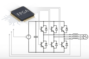
Control algorithms for power electronics converters often rely on PI controllers executed on the CPU of the controller. That’s the technique used in most of the application notes on this knowledge. However, in some situations, it could be desired to run the control loop on an FPGA (e.g. to offload the CPU, or achieve much faster control rates). In that case, it is required to develop an FPGA-based PI controller.
The implementation of an FPGA-based PI controller is given as an example in the introductory notes to Vitis HLS and Model Composer. These are the two recommended approaches to develop FPGA-based control routines. In most realizations, however, the control of three-phase AC variables requires two PI controllers running in a synchronous reference frame (dq), as introduced in the note about CPU-based vector current control.
This page gives an example of an FPGA-based dq PI controller for current control of a grid-tied three-phase inverter using both Vitis HLS and Model Composer approaches. Testbenches are also presented and help to validate that the implemented code or model behaves as expected, before even executing it on a real-time controller.
To find all FPGA-related notes, you can visit FPGA development homepage.
Overview of the dq current control module
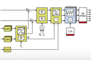
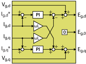
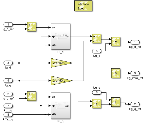
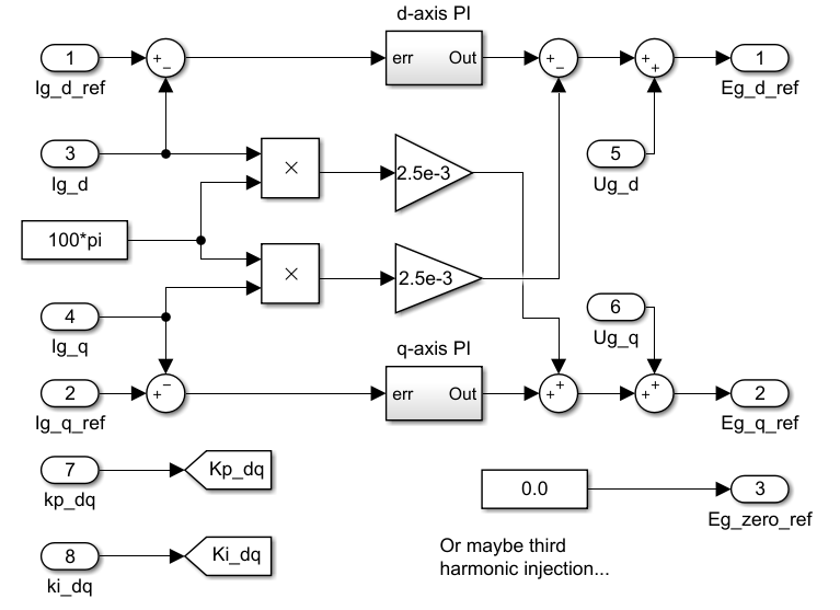
The implemented algorithm is a traditional vector (dq) current control, including a PI controller on each axis and a decoupling network. The measured grid voltages are feedforwarded right after the current controllers, giving voltage quantities \(E_{g,dq0}\) that the converter should generate to induce the desired current. The zero-sequence voltage is here set to zero but can be used for instance for third-harmonic injection, as done in the TN146.
The following sections detail how to pack that algorithm into the FPGA IP shown below, using both High-Level Synthesis tools Vitis HLS and Model Composer. That IP uses AXI4-Stream inputs and outputs to be compatible with other IPs developed on other pages, as well as with Xilinx IP cores for Vivado. In particular, this IP is meant to be connected to the grid synchronization IP developed in FPGA-based grid synchronization.
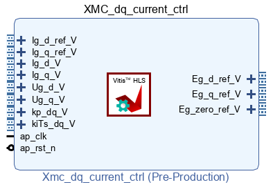
Further details on integrating a Vivado IP in the FPGA are presented in High-Level Synthesis integration into the FPGA. A complete converter control algorithm that uses that IP is presented in FPGA-based converter control.
FPGA-based dq current control using Model Composer
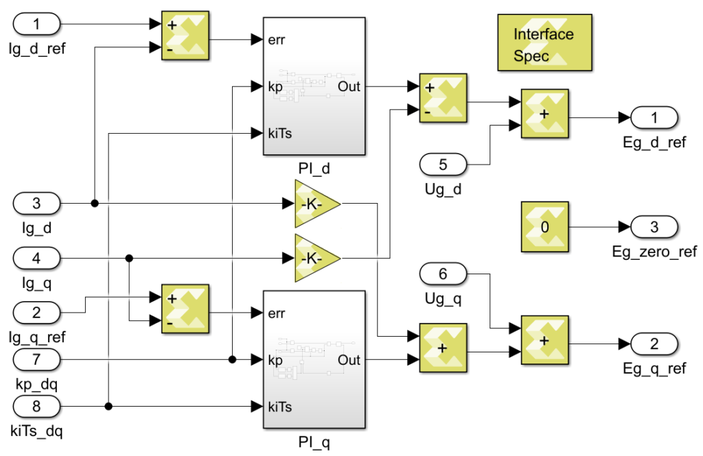
The Model Composer implementation of the FPGA-based vector current controller is shown below.
For more details on how to generate an IP and how to integrate it to the FPGA of imperix controllers, please refer to the introductory note to Model Composer.
Testbench of the Model Composer implementation
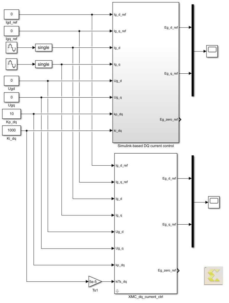
Model Composer allows the user to test his implementation directly from within Simulink in an offline simulation. For comparison purposes with the Vitis HLS approach, the same inputs as the Vitis testbench are fed to the Model Composer model.
A previously-validated Simulink implementation of the vector current controller serves as a reference for both Vitis HLS and Model Composer testbenches.
FPGA-based dq current control using Xilinx Vitis HLS
The complete Vitis HLS sources of the FPGA-based vector current controller can be downloaded below:
Below is the C++ code of the algorithm used in this example, for reference. From there, this code can be used to generate an IP and integrate it into the FPGA of an imperix controller, following the instructions of the introductory note to Vitis HLS.
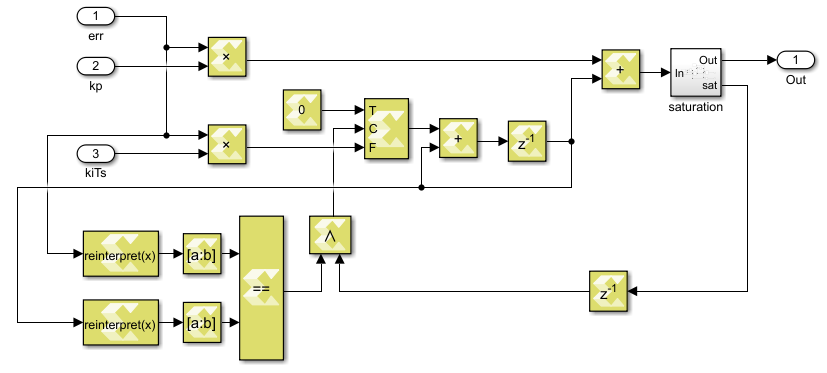
Note that the integrators are represented as accumulators, using static variables. The directive #pragma HLS RESET is used to control the reset of integrators (e.g. when the control is not active, the integrator should be kept at reset). Since the polarity of the reset signal will be automatically set to active low when using AXI4, it is not necessary to specify it explicitly.
Note also that in the codes above, the integral gain is \(K_{i}T_{s} \) instead of \(K_{i} \), which means that in the Vivado project, a floating-point multiplier is needed to compute \(K_{i}\cdot T_{s} \) before this module. The reason to do this is not technical, but just to be consistent with the Model Composer implementation (see below), which is limited to 8 input/output ports.
Testbench of the Vitis HLS implementation
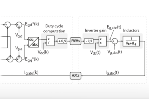
Simulating the closed-loop control behavior of the developed current controller in Vitis HLS is uneasy since it would require a model of the control process (i.e. model of the PWM modulators, of the power converter, and of the acquisition of the measurements). Instead, we can run the Vitis HLS controller using the same input signals as an already-validated Simulink model, and validate the implementation by comparing the results.
The input signals of this testbench are the following two sine signals (the other inputs are kept constant for simplification):
$$ \begin{aligned} &I_{d}=5\sin(100\pi \cdot nT_{s}) \\ &I_{q}=5\sin(100\pi \cdot nT_{s}+\frac{\pi}{2}) \\ &n=0,1,2,…,999 \\ &T_s=5\times 10^{-5} \end{aligned} $$
The simulation results are stored in a CSV file and plotted with MATLAB on top of the results of the Simulink (and Model Composer) models for comparison. The comparison is done at the bottom of this page.
The testbench is executed using the following code:
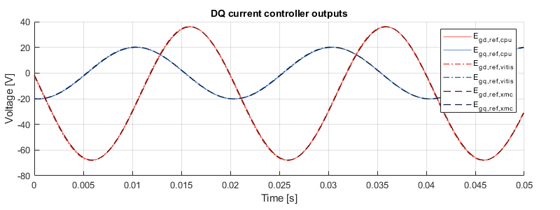
Testbench results
The graph below shows that all three implementations have the same behavior, which validates that the Vitis HLS and Model Composer implementations are correct.
Further readings
A similar approach is used in the implementation of a grid synchronization module for the FPGA. Both these IPs are used in FPGA-based converter control.