Table of Contents
Taking a Three-phase PV inverter as a reference application, this note provides programming essentials for the CPP SDK to facilitate the implementation of full-scale converter control algorithms. While foundational C++ development is covered in the Getting started with the CPP SDK, this page focuses on providing guidelines and practical code snippets to go further with programming using the CPP SDK.
Specifically, this article addresses common power electronics control strategies, state machine management, background tasks for multirate control, communication interfaces, and control validation recommendations. The provided example encapsulates all of these concepts, serving as a comprehensive reference and a robust foundation for CPP SDK developers.
CPP SDK programming insights
When developing a new control algorithm for imperix controllers, the following two-step workflow is recommended to get started efficiently:
- Software documentation: Users should refer to the software documentation and/or the CPP SDK header files to understand the available hardware peripherals and corresponding software routines.
- Peripherals and control: It is recommended to first configure the peripherals in the initialization routine. Then, the control algorithms can be implemented within the main real-time loop.
Development Tip: To bridge the gap between the basic template and a functioning system, it is recommended to draw inspiration from existing imperix examples. Even ACG-based examples provide valuable reference for control strategies.
With this mindset, this page dissects the C++ control file from the Three-phase PV inverter for grid-tied applications example, as it covers most of the essential programming insights needed to use the CPP SDK. The complete C++ project is provided below.
For additional details regarding the converter topology and the control strategy, users can refer to the aforementioned article.
Common power electronics control strategies
To facilitate the development of control algorithms, the CPP SDK includes a dedicated API folder with pre-validated power electronics functions, such as PI controllers, PLLs, and coordinate transformations. Developers are encouraged to use these standard functions, which they can modify as needed.
The following few paragraphs will showcase how to use a few of the provided functions.
State machine implementations
Power converter control often requires managing different operational states, such as standby, precharging, operating, discharging, fault, and many more. State machines are powerful tools that allow to manage these transitions safely.
They can be implemented in many ways. The following snippet serves as a practical example. It details the state machine handling the different operational states of the PV inverter.
Programmatic activation of PWM signals
Following the implementation of a state machine, developers may look to automate the activation of PWM signals. While this action is usually performed manually via the dedicated Cockpit button, it is possible to do it programmatically, using the CoreStart() and CoreStop() functions. When combined with state machine logic, these functions enable fully automated converter operation.
/**
* /!\ Caution /!\
* Please check that the B-Box hardware protection limits are properly configured
* to avoid causing irreversible damage to the converter.
*/
if(enable_pwm) CoreStart();
else CoreStop();Code language: C++ (cpp)System logging and diagnostics
User log messages are highly useful for tasks such as tracking state machine transitions or reporting converter faults. These messages can be configured and displayed in Cockpit using the Log_AddMsg and Log_SendMsg functions.
However, simply placing Log_SendMsg inside the main interrupt will continuously spam the Cockpit Log tab at the interrupt’s operating frequency, eventually overflowing the buffer. To avoid this, developers must implement logic to generate discrete trigger events. The following code demonstrates one approach to trigger these logging messages.
Background tasks and multirate control
Tasks such as MPPT, thermal monitoring, or background communication may not require execution at the strict, high-frequency rate of the primary control interrupt. To manage computationally heavy or slow-rate tasks, the CPP SDK provides a background callback routine, typically implemented as UserBackground() that executes during the CPU’s idle time.
For this specific PV inverter application, the background routine is used to implement an MPPT algorithm executed at 200Hz and is detailed below.
To set up a background loop with the CPP SDK, it is first required to declare a background loop function prototype:
// Background loop prototype
tUserSafe UserBackground();Code language: C++ (cpp)
This function then needs to be registered during the initialization routine in UserInit();
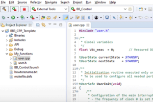
tUserSafe UserInit(void){
  /**
   * Configuration of the main interrupt:
   * - CLOCK_0 is set to the desired frequency
   * - The main interrupt is mapped on CLOCK_0.
   * - Register the background loop function
   */
  Clock_SetFrequency(CLOCK_0, SW_FREQ);
  ConfigureMainInterrupt(UserInterrupt, CLOCK_0, 0.5);
  RegisterBackgroundCallback(UserBackground);

  //  ...
}Code language: C++ (cpp)
The background loop is executed as fast as possible during the CPU’s idle time. It runs with a lower priority than the main interrupt and therefore does not compromise the deterministic execution of the real-time control interrupt.
While its base execution rate is unguaranteed, developers can easily implement multirate control by using a software timer inside the main interrupt. This timer would raise a flag to trigger the background task at periodic intervals, as shown below:
void User_BackgroundLoopTimer(){
  // Increment timer and trigger flag for background loop
  SubTaskTimer += SAMPLING_PERIOD;
  if(SubTaskTimer >= MPPT_PERIOD){
    SubTaskTimer = SubTaskTimer - BACKGROUND_LOOP_PERIOD;
    SubTaskFlag  = true;
    }
}Code language: C++ (cpp)
Finally, the background loop function can be defined to execute only when the periodic flag is raised:
// Background loop function
tUserSafe UserBackground(){
  if(SubTaskFlag){
    // Insert your code here

    SubTaskFlag = false;
  }
  return SAFE;
}Code language: C++ (cpp)
Software user faults
While hardware protections handle instantaneous electrical limits, additional safety conditions, such as communication timeouts or failed precharge sequences, may require software-defined faults.
For this, the CPP SDK allows users to trigger custom software faults using the SetUserFault(const char* user_txt) function. These faults are integrated directly into the fault manager of imperix controllers. When triggered, they immediately disable PWM signals (although not as rapidly as hardware protections) and can display a custom message in the Cockpit logs. The controller will remain locked in the FAULT state for as long as this function is actively called.
    if(V_meas > V_max){
        SetUserFault("Maximum voltage exceeded");
    }Code language: C++ (cpp)
As an alternative, it is also possible to trigger a user fault by returning the state UNSAFE within the user interrupt. Returning SAFE implies that no errors happened during execution.
Note that returning UNSAFE will generate a generic fault. It is then usually recommended to use the SetUserFault(const char* user_txt) method to be able to display a specific fault message.
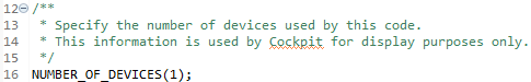
Specifying the number of devices used
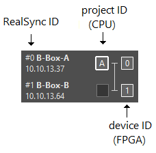
Since SDK 2025.1, as shown in the image below, Cockpit reads how many devices are used by the user code to properly display the assignment between the user code (project) and targets.
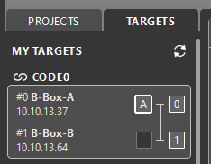
When using the ACG SDK, the number of used devices is automatically retrieved. With the CPP SDK, however, users must explicitly specify this information using the NUMBER_OF_DEVICES macro, as illustrated below. This is particularly needed when developing code intended for multiple targets, as the default value is set to one.
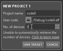
Alternatively, this information can be manually edited from Cockpit, using the No. of devices field.
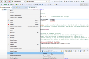
Right-click on the project → Index → Rebuild. This resets the project’s code cache and wipes away the false warning lines.
Control validation and debugging
Because offline simulation is not available for CPP SDK users, the developed control must be validated directly on the physical hardware. Consequently, it is strictly even more critical to configure robust hardware and software protections prior to testing (refer to Over-current and over-voltage protection documentation). Indeed, without a simulated environment, development relies heavily on incremental physical validation.
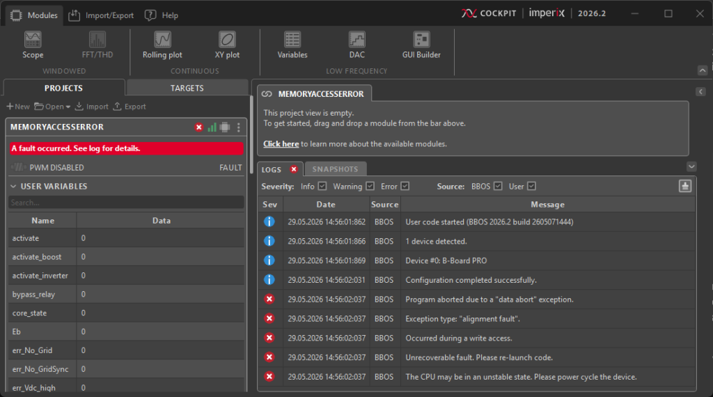
Memory access errors
Memory access violations occur more frequently when using the CPP SDK, most often due to the misuse of pointers in C++. When an invalid memory address is accessed, a hardware exception is triggered by the processor (further details can be found in the ARM Cortex Fault Handling documentation). When such an event is triggered:
- The CPU is safely hard-locked so that erratic control behavior is prevented.
- A fatal error message detailing the fault is displayed within the Cockpit logs.
- A restart of the controller is required for system recovery.
To guarantee system safety during these CPU lockups, imperix controllers are equipped with a dedicated FPGA Watchdog. In the event that the CPU becomes unresponsive, in the case of a hardware exception for instance, this watchdog automatically intervenes to immediately disable all active PWM signals, ensuring no hardware damage.
Further readings
- Programming and operating imperix controllers (PN138) is a guide for deploying code onto imperix controllers
- Cockpit user guide (PN300) gives an overview of the tools provided by Cockpit and how to use them