Table of Contents
In recent years, the demand for renewable energy sources has grown significantly, with solar energy emerging as one of the most promising and widely implemented options. In residential and small-scale commercial applications, most PV systems are designed to feed their energy into the electrical grid, often with a single phase connection.
Since PV panels generate DC power, a power conversion stage is required to transform it into AC, suitable for grid injection. This conversion can be done using a single or multiple inverters. In the literature, various topologies have been developed and introduced [1, 2]. In many cases, an intermediate DC/DC boost stage is required between the PV panel and the grid to achieve sufficient voltage. This allows the implementation of maximum power point tracking (MPPT) control, ensuring that the PV panel operates at its optimal power point. Although it offers some decoupling between the PV operating point and inverter control, the active power flows remain coupled.
Among all topologies, the combination of a boost converter and a full-bridge single phase inverter is widely adopted, corresponding to the schematic in Fig. 1. Compared to more complex topologies, this configuration offers a good balance between simplicity, cost-effectiveness, and performance. When combined with a low-frequency transformer, it also provides galvanic isolation, enhancing system safety and facilitating the grounding of the PV side. Other converter topologies, such as the single phase totem-pole inverter, can also be implemented; however, they typically introduce additional complexity in terms of control and design.
In this application note, the control implementation of the PV systems is explained, followed by the presentation of simulation and experimental results.

PV-side control implementation
In this case, a boost converter is used as the DC/DC converter connected to the PV side, which enables boosting the DC voltage generated by the PV panel up to the intermediate DC bus voltage. A detailed description of the boost converter and its working principles is provided in TN101. The closed-loop control block diagram is shown in the figure below.
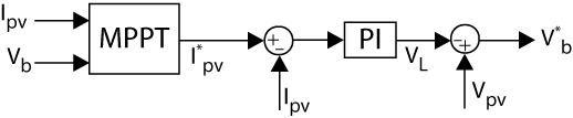
As illustrated, the PV current is regulated using a conventional PI controller, which can be tuned following the same principles described in TN109. The equations for the boost converter are similar to those used for the buck converter, where the main difference lies in the expression for the voltage drop across the inductor. For the boost converter, this relationship is given by the following equation:
$$ (1)\quad V_L = V_{b} – V_{b}^*$$
Finally, an MPPT is used to calculate the current reference of the PV side. This algorithm is implemented to ensure that the PV panel operates at its maximum power output. More detailed information about the MPPT can be found in TN117.
Grid-side control implementation
The grid side control implementation of a single phase inverter is formed of three main parts, which are explained in detail below: the grid synchronization, the current controller, and the DC bus voltage control. In this application, three-level modulation has been used.
Grid synchronization
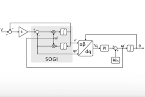
In the control of AC/DC converters, grid synchronization is essential to ensure the independent control of the active and reactive power flows. For single phase inverters, this synchronization can be achieved using various control techniques, with the phase-locked loop (PLL) being the most commonly implemented. Additionally, several PLL-based methods are discussed in the literature [3]. In this case, the SOGI-based PLL has been selected due to its strong immunity to harmonic disturbances, which are common in such applications. More detailed information about the different grid synchronization methods for single phase inverter can be found in TN107.
Current control
The control of single phase systems differs substantially from that of three-phase systems. In particular, many well-established concepts—such as the decoupling of the direct and quadrature axes, which are associated with active and reactive power flows—cannot be directly obtained through coordinate transformations due to the presence of only a single phase. Consequently, when independent control of power flows is desired, a fictitious β-axis is introduced, enabling the application of vector control techniques.
Two main categories of controllers are commonly implemented: PI controllers and PR controllers.
PR controllers are used to control systems with sinusoidal behaviour. Consequently, it has the benefit of not needing to implement any fictitious system to control the single phase inverter. However, the decoupling of active and reactive power flows is less intuitive. In TN113, an example of a single phase totem-pole rectifier controlled with a PR controller is presented.
PI controllers, in contrast, are effective for controlling DC quantities, as their integral action provides infinite gain at DC, ensuring zero steady-state error. When tracking sinusoidal AC signals, their finite gain at the fundamental frequency leads to persistent steady-state error and a delayed response. In single phase systems, PI control is typically implemented in a dq rotating reference frame synchronized with the grid, requiring fictive-axis emulation (FAE) to reconstruct the missing \(\beta\)-axis. This approach enables effective decoupling of active and reactive power flows and allows reuse of control strategies from three-phase systems.
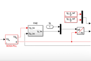
In this case, the control is implemented using the dq-based vector current control, where the \(\beta\)-axis is estimated using the FAE method.
DC-bus voltage control
The DC bus voltage control is implemented using a conventional cascaded voltage control (TN108). A feed-forward current term derived from the PV side is also included to improve dynamic performance by anticipating changes in PV power, allowing the inverter to adjust its output current more effectively and thereby improving the quality of current injection into the grid.
In single phase grid-connected PV systems, a DC bus ripple arises from the inherent power fluctuations at twice the line frequency (double-line frequency). This ripple can lead to the controller instability, and reduced power factor in the system. To mitigate this double-frequency components in the controller output, one method is to reject the power ripple at the double-line frequency by limiting the controller’s bandwidth to below this frequency (e.g., below 100 Hz for a 50 Hz grid). This approach is detailed in the outer-loop tuning section of TN113. Alternatively, a notch filter can be inserted at the controller’s error input, which is the method used in this note to reject the power ripple at twice the line frequency, which is implemented using a SOGI filter.
Simulation results of single phase PV inverter
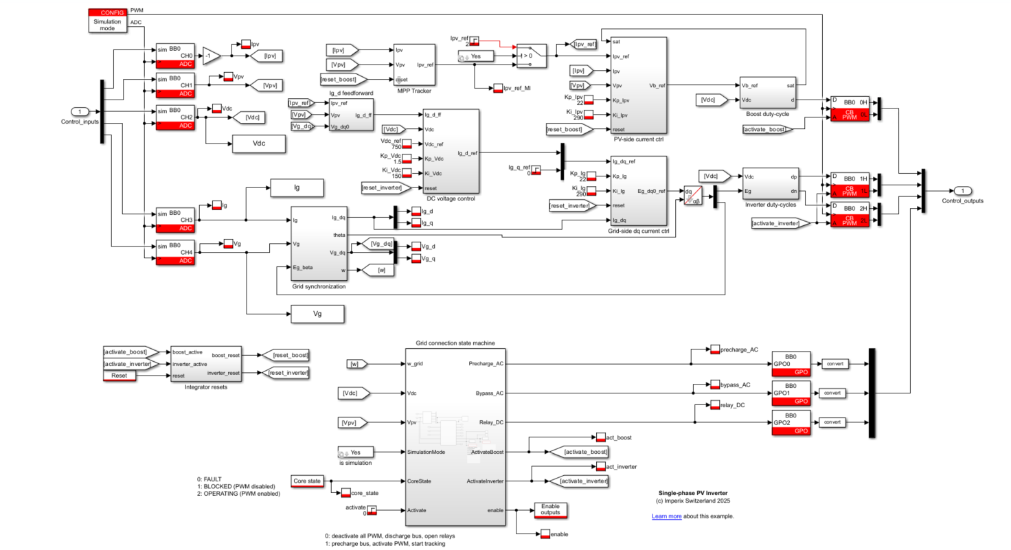
The control of the single phase PV system is implemented on MATLAB Simulink using the imperix power library (part of imperix ACG SDK). The model is compatible with Matlab 2019a or newer versions and can be downloaded from the following link:

The main objective of the simulation is to demonstrate that the controllers can accurately track the references and are correctly implemented. Since the dynamics of the MPPT are very slow, it does not make much sense to implement it in the simulation and, therefore, the current reference is set using a tunable parameter.
The obtained results are shown in Fig. 3, where some transients in the active and reactive power setpoints are implemented. It can be observed that the current controllers for both the boost and the single phase converters correctly follow the current reference. Moreover, when a reference step is applied to the PV-side current (\(I_{pv}\)), the AC-side current setpoint (\(I_{d*}\)) is quickly adjusted, thanks to the feed-forward term. This minimizes the impact on the DC bus voltage, which is maintained within a tight voltage band. Additionally, the previously mentioned double-line-frequency component at 100Hz can be observed in the DC bus voltage, which doesn’t impact the AC-side current setpoint, thanks to the implemented notch filter.

Experimental results
Required hardware
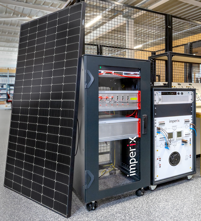
The experimental setup is shown in Fig. 4 and the following list describes the required hardware. It comprises imperix products as well as additional components commonly available in power electronic research laboratories.
- Imperix products
- 1x programmable controller (B-Box 4)
- 3x half bridge power modules
- 1x passive filter box
- 1x grid connection panel
- Control development tools for Simulink and PLECS (ACG SDK), with a valid license
- Additional hardware
- 1x DC relay
- 1x 50Hz isolation transformer
- PV solar panel or PV panel emulator
- Safety laboratory cables (banana)
Front-end configuration
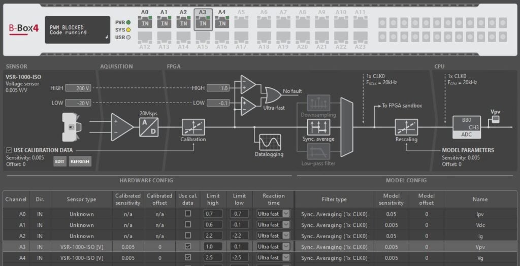
When using the B-Box 4 as the controller, the front-end panel can be configured using Imperix Cockpit. In this example, the selected limits for each measured signal are shown in Fig. 5. More information on how to configure the front-end panel can be found here.
Experimental results
To experimentally validate the proposed control strategy, two PV panels (SOLYCO Solar R-BF 108p.3 405W FB), each rated for 400 W, are connected in series at the input of the boost converter. A 50 Hz isolation transformer is used on the AC side of the single phase inverter to interface it with the grid. Both converters are interconnected through the DC bus, as illustrated in Fig. 1.
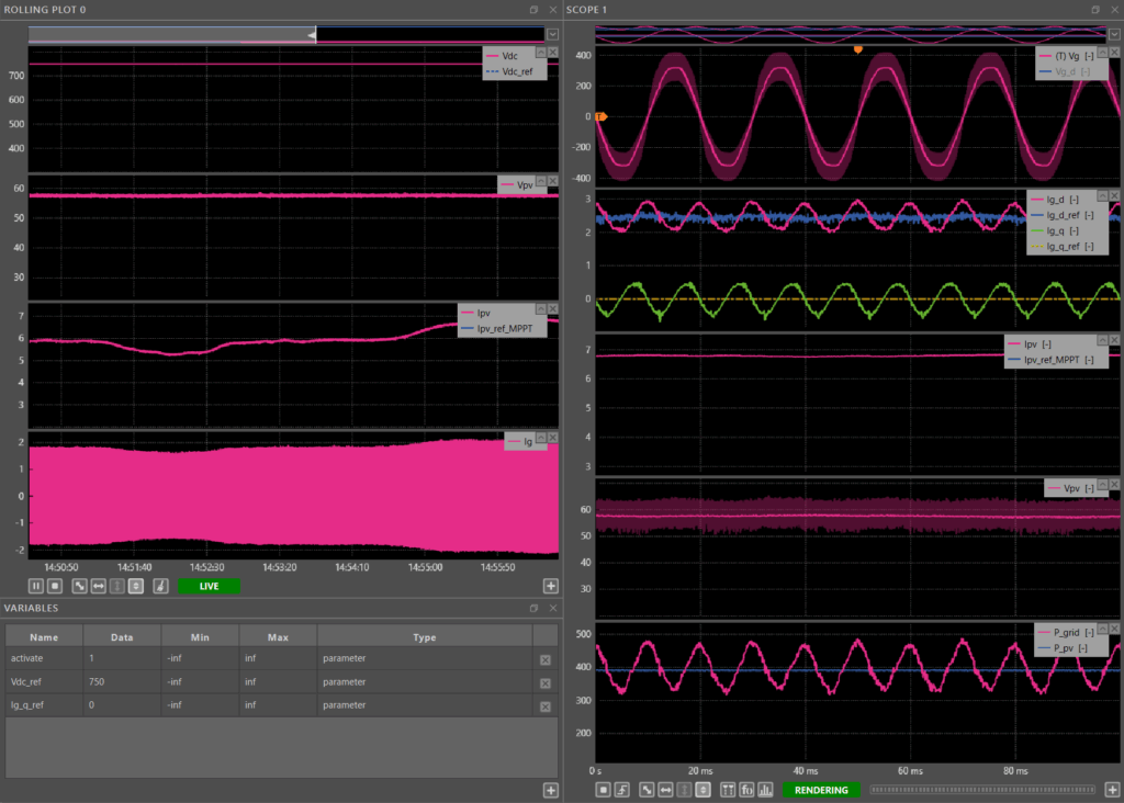
The system’s operation begins when the activate variable is set to 1, initiating the precharge and activation sequence through the system’s state machine. Figure 6 presents the experimental results obtained under partially cloudy conditions.
The rolling plot shows that the MPPT algorithm dynamically adjusts the PV current reference (Ipv_ref_MPPT) to extract the maximum available power from the PV panel. The PV voltage (Vpv) remains nearly constant, which aligns with the expected behaviour of the PV characteristic curve under MPPT control. The variation in the PV current (Ipv) corresponds to changes in solar irradiance. Moreover, due to the feedforward control, variations in the PV current directly influence the grid current (Ig), ensuring that power transfer to the grid remains smooth and responsive to PV generation changes.
In the scope module, the current control loops demonstrate accurate tracking performance; both the grid current (Ig) and the PV current (Ipv) follow their respective reference signals effectively.
Finally, it can be observed that the average AC power closely matches the DC power. The AC and DC power values were computed using the Cockpit formula builder. The ripple observed in the grid currents and AC power is attributed to the double-line-frequency pulsation inherent to the single phase inverter.
Conclusions
In this work, a grid-connected single phase PV system has been implemented. The grid connection is achieved using an isolation transformer, and synchronization is performed through a SOGI-based PLL, chosen for its strong immunity to harmonic disturbances. The grid-side control employs a cascaded control structure responsible for regulating both the DC bus voltage and the grid current. To enhance the dynamic performance of the DC bus voltage control, a feed-forward current term derived from the PV panel has been incorporated. Furthermore, a three-level modulation strategy is used for the single phase inverter, which effectively reduces the current ripple and harmonic content.
The MPPT algorithm must be properly tuned to ensure that the perturbation step size is sufficiently small to minimize undesired oscillations in the current reference. Additionally, its update frequency should be significantly slower than the current control bandwidth. If the MPPT updates too frequently, the current controller may not settle before the reference changes again, causing tracking errors or instability.
References
[1] S. B. Kjaer, J. K. Pedersen and F. Blaabjerg, “A review of single-phase grid-connected inverters for photovoltaic modules,” in IEEE Transactions on Industry Applications, Vol. 41, 2005.
[2] S. Kouro, J. I. Leon, D. Vinnikov and L. G. Franquelo, “Grid-Connected Photovoltaic Systems: An Overview of Recent Research and Emerging PV Converter Technology,” in IEEE Industrial Electronics Magazine, Vol. 9, pp. 47-61, 2015.
[3] R. Teodorescu, M. Liserre, and P. Rodriguez, “Chapter 4 – Grid Synchronization in Single-Phase Power Converters,” in Grid Converters for Photovoltaic and Wind Power Systems, John Wiley & Sons, 2011, pp.43-91.