
Table of Contents
This document provides instructions for configuring CPU-based multi-rate control for imperix controllers using Simulink with the ACG SDK. It allows executing part of the control algorithm at a slower rate to optimize CPU utilization. This approach is typically useful for executing supervisory logic, slow outer control loops, energy management routines, or MPPT algorithms, while keeping maximum CPU capacity for fast inner control loops.
This page provides configuration instructions specific to Simulink. PN265 provides a more general introduction to multi-rate control.
Single-tasking and multitasking configurations
By default, Simulink code generation processes multi-rate models using multitasking mode. This means the code generator places each discrete sample time into a separate task (technically a distinct function). When deployed on imperix controllers, this translates into priority-based task scheduling with preemption, as detailed in PN265.
Simulink generates code for either single-tasking or multitasking execution based on the model configuration parameter Treat each discrete rate as a separate task. To modify this parameter:
- Set the Execution purpose parameter in the CONFIG block to Automated Code Generation (this setting is hidden in simulation mode).
- Open Model Configuration Parameters (Ctrl+E) and navigate to Solver > Solver details.
- Select or deselect Treat each discrete rate as a separate task based on the expected behavior:
- Checked for multitasking mode
- Unchecked for single-tasking mode
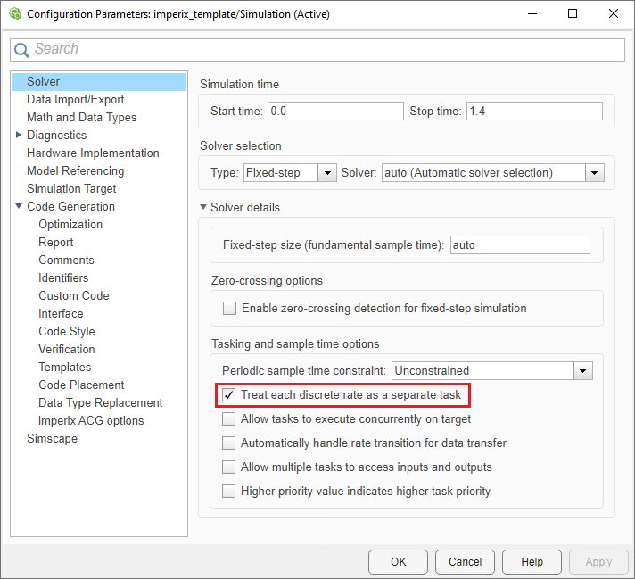
Rate configuration
In Simulink, different execution rates are defined by their Sample Time. The base-rate sample time is set via the CONFIG block (calculated as the CLK0 frequency divided by the optional postscaler). Any block configured with this base sample time generates code that executes at the CPU interrupt rate.
Additional sample rates can be derived from the base rate, either by configuring the Sample time parameter directly within individual blocks, or by placing a Rate Transition block between different rate domains.
Base rate and sample-time constraints
In Simulink, the model’s base rate is determined from the sample times defined in the model. Simulink computes a common base period from these sample times, allowing the different rates to be scheduled as integer multiples of this base rate. When deploying the model on an imperix controller, the process assumes that the rate Simulink identifies as the base rate is the rate at which the CPU interrupt is triggered.
This correspondence can be broken if a model rate is defined with a period that is not an integer multiple of the CLK0 period. In this case, Simulink computes a faster common base rate to accommodate all model rates. Since no hardware interrupt is configured at that faster base rate, the resulting model cannot be deployed, and Cockpit will throw the error “The control task period set in the CONFIG block is different from Simulink’s fastest discrete period D1“.
Consequently, all model sample times should be chosen as integer multiples of the CLK0 period. The interrupt period is available through the CTRLPERIOD variable, so it is recommended to define sample times as CTRLPERIOD(1) × N, where N is a positive integer.
(1) index is used because CTRLPERIOD may be a vector when a non-zero sampling phase is configured, as described in Simulation essentials on Simulink.Rate Transition block
As explained above, the Rate Transition block is the go-to block for introducing additional execution rates while properly managing data transfer between different rate domains. An illustrative example of use is shown below.
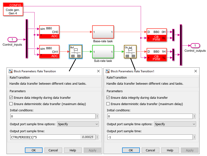
The recommended configuration parameters of the Rate Transition blocks are:
- Output port sample time: the rate of the subrate task. To avoid the issue mentioned in the previous section, it is advised to set this rate with:
- Option 1:
CTRLPERIOD(1)*Nwith N being the desired decimation ratio - Option 2: set Output port sample time options to Multiple of input port sample time and specify the decimation ratio in Sample time multiple
- Option 1:
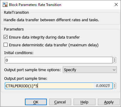
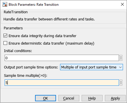
- Ensure data integrity during data transfer: Leave this parameter checked at all times to avoid data corruption that may occur during preemption.
- Ensure deterministic data transfer: To avoid the induced data transfer delay this introduces, this parameter can be unchecked. Disable this parameter when a non-zero sampling phase is configured in the CONFIG block, since Simulink does not allow it to be enabled with non-zero sample-time offsets.
More information about these concepts is available directly in MathWorks’ documentation: mathworks.com/help/simulink/slref/ratetransition.html
Application example
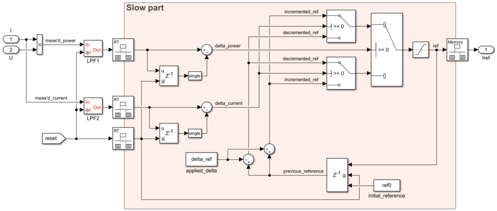
An example of use is presented in Maximum Power Point Tracking (MPPT) (TN117). It shows how one part of the control (in red in the figure below) can be executed at a slower rate than the main control code.
 By Julien Orsinger • March 29, 2021 • PN142
 By Nicolas Cherix • March 25, 2021 • TN117
 By Stéphane Lovejoy • March 25, 2021 • PN155