Table of Contents
This page outlines the configuration methods for analog I/O channels on imperix controllers. While digital I/Os are configured exclusively via software and remain consistent across all controllers, analog I/Os require configuration both through software and through hardware, directly on the target device, which varies by controller model.
The following sections provide an overview on how to configure both types of settings on different imperix controllers.
Hardware configuration
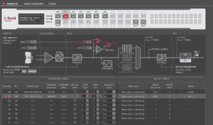
Hardware settings vary by controller model. Configuration is performed via the front-panel interface (screen and button) or Cockpit, depending on device compatibility. The table below summarizes the possible analog I/O hardware configuration methods and provides references for each controller.
A detailed comparison of imperix controllers, highlighting their hardware differences, is available in the article about How to choose between imperix controllers.
|
Controller |
Configurable through |
Detailed configuration instructions |
|---|---|---|
|
B-Box 4 |
Front-panel screen, |
|
|
B-Box 3 RCP |
Front-panel screen |
|
|
B-Board 3 PRO |
N/A |
Analog chain design and configuration left to the user |
|
B-Box 3 micro |
Cockpit remote view |
|
|
TPI 8032 |
N/A |
Over-current, over-voltage, and over-temperature thesholds are configured automatically. More details are provided in Getting started with the TPI 8032 |
Software configuration
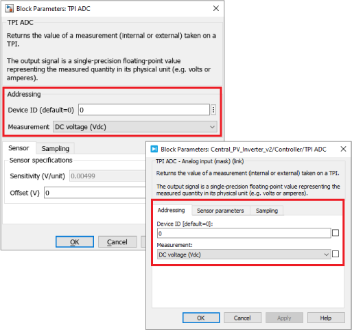
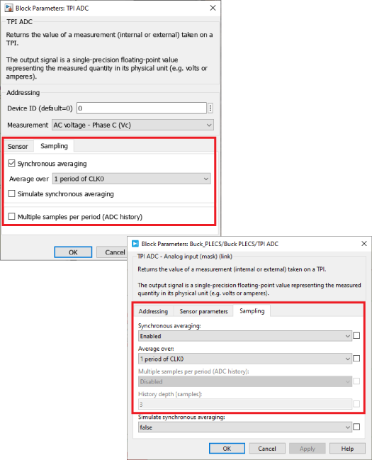
Software settings are configured from the user code and are compatible across controllers, with minor hardware-specific variations. In Simulink and PLECS, these settings are configured using the ADC block (for B-Box/-Board controllers) or the TPI ADC block (for the TPI8032). The main software settings are described below.
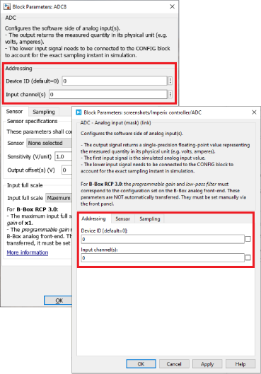
Addressing
- The Device ID defines which device is addressed when a multi-device configuration is implemented. With a single controller, the default ID must be used, which is 0.
- The Channel number (B-Box/-Board only) selects from which physical input data is read. The vector notation (e.g. [0:2]) can be used if multiple channels are desired to be configured identically.
- The Measurement (TPI8032 only) offer the same selection mechanism, but as a function of the measured variable. The sensor type is also set automatically. The hardware resources mapping is given in SD200.
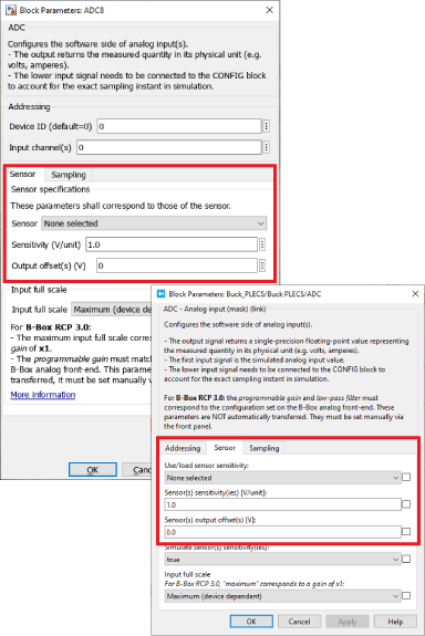
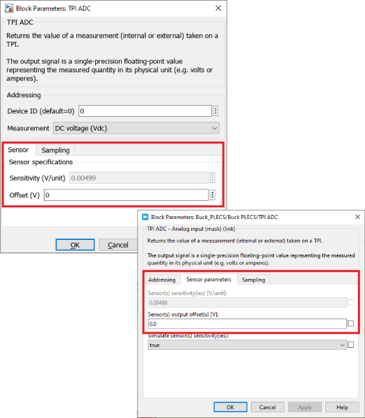
Sensor specifications
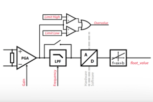
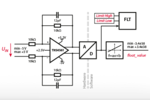
- A list of imperix Sensors is provided to facilitate the configuration. Chosing a sensor automatically sets the corresponding sensitivity. This information is used so that the raw ADC value – a 16 bits integer – is transformed into a meaningful floating-point quantity (e.g. 230.6V) before processing in the CPU. If necessary, an offset can also be indicated, and compensated for during the same conversion.
- On the TPI 8032, the sensor type is automatically selected once the Measurement is chosen.
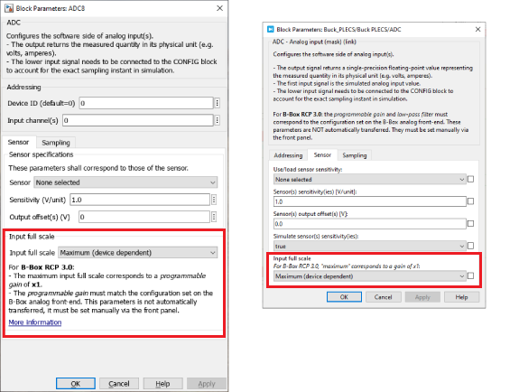
Input full scale
- The Input full scale only applies to B-Box/-Board controllers. Two options can be selected: Maximum (device-dependent) and Programmable (B-Box RCP 3.0 only). The device-dependent setting automatically accounts for the controller model. If the Programmable setting is selected for the B-Box RCP 3.0, the same gain must also be manually configured at the hardware level using the front panel (see PN105).
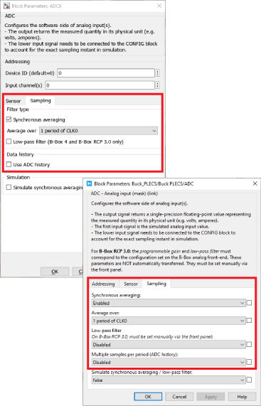
Sampling
All imperix controllers always sample across all channels and devices simultaneously. For this reason, the Sampling frequency and phase is a common setting located within the CONFIG block. On the other hand, filtering or down-sampling strategies are configured on a per-channel basis. The available options are:
- Synchronous averaging. This computes the average of multiple samples over one or two PWM periods. This technique is the default recommended strategy. It is available for all controller models.
- Low-pass filter (B-Box 3 and 4 only). This is a software parameter on the B-Box 4 (configured inside the model), but a hardware parameter on the B-Box 3 (configured using the front panel).
- Data history. This provides a vector containing the N most recent ADC samples. This generally makes most sense when used with a Postscaler between the effective sampling and CPU execution rates.
If none of the above options are selected, regular synchronous sampling is used.
Going further
Detailed information about the analog I/O configuration for each controller can be found in:
- Analog I/O configuration on B-Box 4
- Analog front-end configuration on B-Box RCP 3.0
- Analog inputs configuration on B-Box Micro
- Getting started with the TPI 8032
For the software settings, the next pages provide more information about the ADC and TPI ADC blocks:
Finally, more information about the operating and programming principles of imperix controllers are provided in the next page: