Table of Contents
This article provides instructions to get started with the CPP SDK, focusing on the workflow associated with the development of C++ control algorithms for imperix controllers. Specifically targeted at first-time users, it notably addresses:
- Product presentation: What the CPP SDK is, and what pieces of software it contains.
- CPP SDK programming workflow: A general overview of the workflow to give a first idea of how imperix controllers are programmed.
- Development with the C++ IDE: An introduction to the C++ IDE and to the structure and content of the user code template.
- Buck converter example: An example initializing and operating the main hardware peripherals, such as ADCs and PWM modulators.
Instructions regarding the initial software installation and setup of the CPP SDK are detailed in PN146.
Product description
The CPP SDK is a Software Development Kit (SDK) for programming imperix controllers using C++ code. It includes:
- An Eclipse-based IDE tailored to program imperix controllers
- The BBOS operating system for the controllers.
- The standard FPGA firmware.
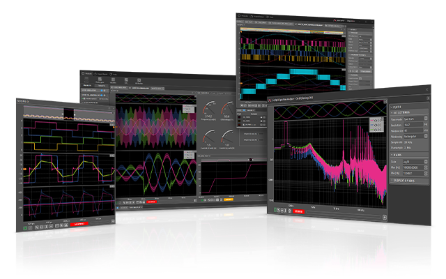
- The Cockpit monitoring software. Cockpit enables real-time interaction and monitoring of the physical converter by providing access to the model variables and all the signals measured by imperix controllers.
Imperix controllers can also be programmed used graphical approaches from Simulink or PLECS, leveraging automated code generation. Users interested in that approach should refer to separate documentation regarding the ACG SDK.
CPP SDK programming workflow
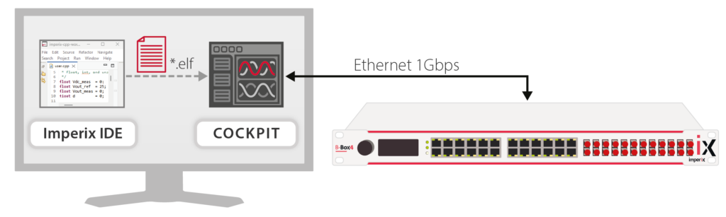
Before diving into control development, it is helpful to get the big picture of the CPP SDK workflow:
- Code development: The control algorithm is implemented within the Imperix IDE (based on Eclipse).
- Compilation: The code is built, and an executable binary file (
.elf) is generated. - Flashing the code: This
.elffile is retrieved by Cockpit and flashed to the controller over Ethernet. - Execution: The executable is loaded and run in real time on the controller.
Navigating the IDE
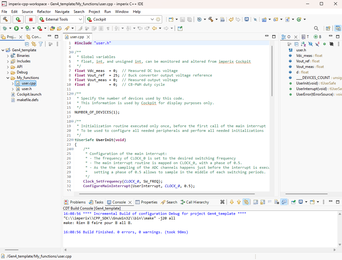
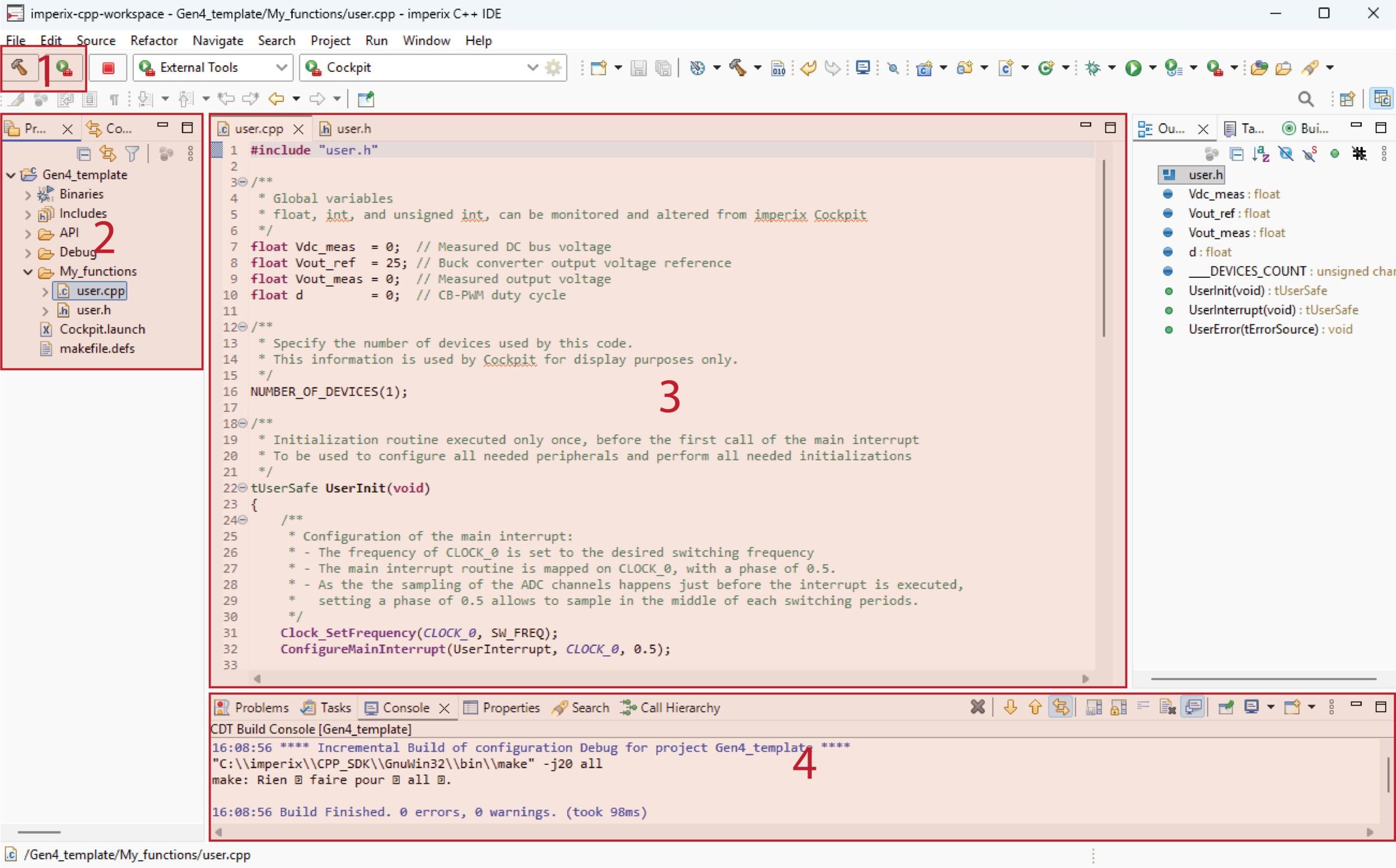
Assuming that the user template is already imported into the workspace, users should be presented with a window as shown in the screenshot below. Instructions to import the user template is provided in the Installation guide for the CPP SDK.
The interface is organized into several key areas as follows:
- Build and launch controls (top left): Dedicated buttons located in the upper-left toolbar are used to compile the code and deploy the executable to the controller.
- Project explorer (left panel): Displays the project’s directory structure and project files. The contents of these files are detailed in the upcoming sections.
- Code editor (center panel): Serves as the main workspace for editing the code.
- Console (bottom panel): Outputs the system logs, displaying any compilation warnings or errors.
User template structure and content
The user template should be imported into the IDE workspace by following the Installation guide for imperix CPP SDK. This template contains several folders, as shown and described below.
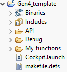
My functions
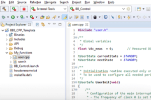
My_functions is the folder where all user files should be stored. By default, it contains only two files:
user.cpp, which serves as the code root. It contains the initialization routineUserInit()and the main interrupt service routineUserInterrupt(). Further details regarding these two functions are provided in the example below.user.h, which typically contains the prototypes of the user-defined routines as well as some useful readability helper definitions.
Includes
The Includes folder contains the header files for the user-accessible routines associated with the hardware peripherals. By reviewing these headers, users can obtain a quick overview of the available routines and the necessary information regarding their implementation. This folder is structured into two main subdirectories: Core and Driver.
The Core folder notably includes routines managing the operational state (FAULT, BLOCKED, OPERATING) of imperix controllers. More information of the related operating principles is given in PN261.
The Driver folder contains the definitions of the peripheral driver routines. All of them are further detailed in the imperix software documentation: https://imperix.com/software-documentation/
API
The API folder provides a predefined routines frequently used in power electronics. Developers are encouraged to use these standard functions, though they can be modified as needed. Key implementations provided within this directory include:
- PI controllers
- MPPT algorithms
- Basic PLLs, such as dq-frame and SOGI
- Coordinate transformations
Developing the user code
This section addresses the development of the user-specific, application-level, part of the embedded software. This starts from the user.cpp file located in the My_functions folder.
Here after, an example is developed, meant to operate a buck converter in an open-loop configuration. The resulting user.cpp file is shown below, with explanations about each section given afterward. Further details can on the application itself can be found in TN100.
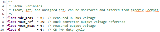
Global variables
The initial segment of the user.cpp file is dedicated to the declaration of global variables. All global variables (of type int, unsigned int, or float) will be available in Cockpit during run time. For the buck converter example, the following variables are instantiated, specifically for this purpose.
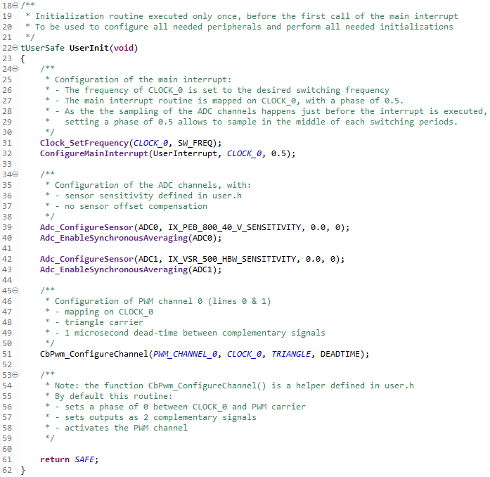
UserInit() function
The next function is UserInit(). This initialization routine is executed only once at startup, prior to the first call of the main interrupt. It is utilized to configure the interrupt timings and initialize all the necessary hardware peripherals. More information about how imperix controllers behave during run-time is given in PN261.
UserInit() notably defines the control period, the sampling phase, and the switching frequency. Comprehensive details regarding the configuration of these clocks can be found in PN259.
For the specific case of the user template, the UserInit() function configures the following:
- Sets the frequency of
CLOCK_0to the desired frequency (e.g. 20kHz). - Maps the main interrupt to
CLOCK_0and sets a sampling phase of 0.5 (the middle of the period) - Configures ADC channels 0 and 1 with the proper sensor sensitivity. More information on the available routines is given in the documentation related to the ADC peripheral.
(Warning: for B-Box RCP 3.0 the configured sensitivity should consider the hardware gain configured input gain on the analog front end. A numerical example is given in PN105.) - Enables synchronous averaging for both ADC channels. More information on synchronous averaging is provided in PN258.
- Initializes a carrier-based PWM peripheral on
PWM_CHANNEL_0. This modulator is mapped toCLOCK_0, is based on a triangular carrier, and is configured with a dead-time of 1 us. More information on the available routines is given in the documentation related to the CB-PWM peripheral.
UserInterrupt() function
The UserInterrupt() routine is executed at the CLOCK_0 frequency, as configured during UserInit(). This function encapsulates the main interrupt-based control routines required to operate the power stage. This generally includes the acquisition of ADC measurements, the execution of control strategies, and the update of the PWM duty cycles. More information on this typical process is given in PN261.
In this example, the UserInterrupt() function simply computes the required duty cycle for the buck converter according to the input voltage measurement. It then updates the output of the PWM modulator.

Note that both the UserInit() and UserInterrupt() functions return the value SAFE when they were executed without errors. Otherwise, the B-Box goes into fault, should an error occur during the execution, or if the value UNSAFE is returned.
Launching the user code
Once the user code has been successfully written and compiled, Cockpit automatically opens up so that it can be flashed onto the controller. The subsequent steps are described in programming and operating imperix controllers and are identical for both imperix SDKs.
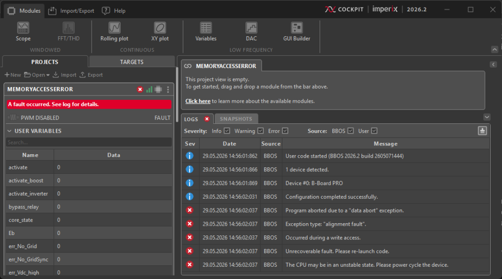
Memory access errors
Memory access violations may easily occur when writing code manually, most often due to misused pointers. When an invalid memory address is accessed, a so-called software fault is detected, immediately holding the blocking all PWM outputs. This is one of many other protection mechanisms available on imperix controllers, as documented in PN263. In such a case, the user code must be restarted.
Further reading
It is recommended to also read the following pages:
- Efficient programming with the CPP SDK provides insights specific to power electronics applications.
- The Cockpit user guide also gives useful hints about how to use the monitoring software.
Additionally, controller-specific getting-started instructions can be found in the following notes: