SV-PWM – Space vector PWM
The SV-PWM block generates PWM signals based on the Space Vector Modulation (SVM) algorithm. This algorithm determines the three vectors that are the closest to…
The SV-PWM block generates PWM signals based on the Space Vector Modulation (SVM) algorithm. This algorithm determines the three vectors that are the closest to…
The FPGA sandbox PWM block allows driving the PWM output from a user-made modulator from within the FPGA. Information on FPGA edition is available on Editing…
The Direct output PWM block sets PWM output(s) directly to ‘0’ or ‘1’. This technique is typically used for Model Predictive Control (TN162) or Direct…
The Carrier-based PWM block generates PWM signals based on one of the 4 carrier shape illustrated below: triangle, sawtooth, inverted triangle, inverted sawtooth. When using…
The Pulse Width Modulators (PWM) share the dead-time generation and the activate/deactivate features, configured through the output mode, deadtime, and activate parameters. The said PWM…
Imperix controllers feature 4 clock generators, CLK0, CLK1, CLK2 and CLK3, running at 250 MHz. They provide time bases for FPGA resources such as the…
The CONFIG block primarily serves to configure the main clock (CLK0) as well as its derivatives. Together, these clocks define the frequency and phase of…

This example implements the control for a three-phase PV inverter. Such a system can be typically found in small industrial photovoltaic facilities, which are directly…
This example generates three phase alternating currents from a voltage source inverter in an open loop manner. It can be used in a grid-forming application.
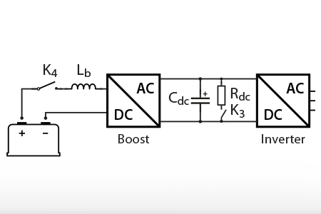
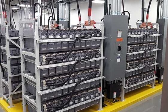
In voltage source converters, pre-charging the inverter DC bus is required before connecting it to external voltage sources, so that to avoid inrush currents that may be destructive.
End of content
End of content