Table of Contents
This note provides tips and tricks on how to speed up Simulink simulation.
1) Avoid unnecessary continuous signals
The control algorithm should be executed at a fixed rate, which corresponds to the main interrupt execution rate. Besides being more accurate, the simulation is also faster if the whole control algorithm is executed at the proper rate. This avoids unnecessary computations, buffering,… caused by the use of different rates.
In practice, this means that the whole control model (between the ADC and the PWM blocks) should be executed at a rate equal to CTRLPERIOD.
Ctrl+J shows the color legend.
Ctrl+D refreshes model.
If unwanted execution rates are present in the model, the proper rate can be enforced by specifying CTRLPERIOD as “Sample Time” of a block. Alternatively, a “Signal specification” block can be used to enforce the execution rate of a specific signal.
See “Mastering the sample times” in note PN135 for more details.
2) Avoid simulating dead-times
Oftentimes, the simulation of dead-times is not necessary to validate a control implementation. Disabling the simulation of dead-times can greatly improve the simulation speed, as this reduces the number of switching events of every PWM channels, and thus reduces the number of steps that the solver has to compute.
In each PWM modulator where the output mode is “Dual (PWM_H + PWM_L)”, the “Simulate dead-time” can be checked or unchecked:
3) Avoid unnecessary variable PWM phases
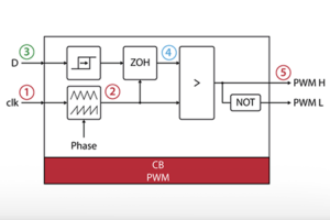
The carrier-based PMW modulators have a simplified and optimized model when a constant phase is used. Therefore, when the desired phase is constant, it should be defined in the corresponding parameter field, and not used as a “Block input”:
4) Use Simulink’s accelerator
For complex systems, Simulink’s accelerator can be of great help. This mode generates a standalone executable and runs it, rather than executing directly the interpreted code of the model, resulting in faster simulations.
5) Close unnecessary scopes
Closing unnecessary scopes, or reducing the number of points displayed in each scope, decreases the amount of necessary resources, and thus increases simulation speed.
Comparative results
The results below illustrate the improvements in simulation speed for the example of the Three-phase PV inverter for grid-tied applications.
| Scenario | Simulation run time (normalized) |
|---|---|
| Accelerator “on” | 0.35 |
| Normal | 1 |
| External constant phase | 1.24 |
| 3 graphs opened (8 variables) | 1.4 |
| Simulated dead-times | 2 |


