
Table of Contents
The article explains how to get started with the TPI 8032 programmable inverter. It provides an overview of the hardware architecture and detailed instructions to program the device. A basic application example with step-by-step instructions is also developed, implementing an open-loop voltage-source inverter with a passive load.
What is the TPI 8032?
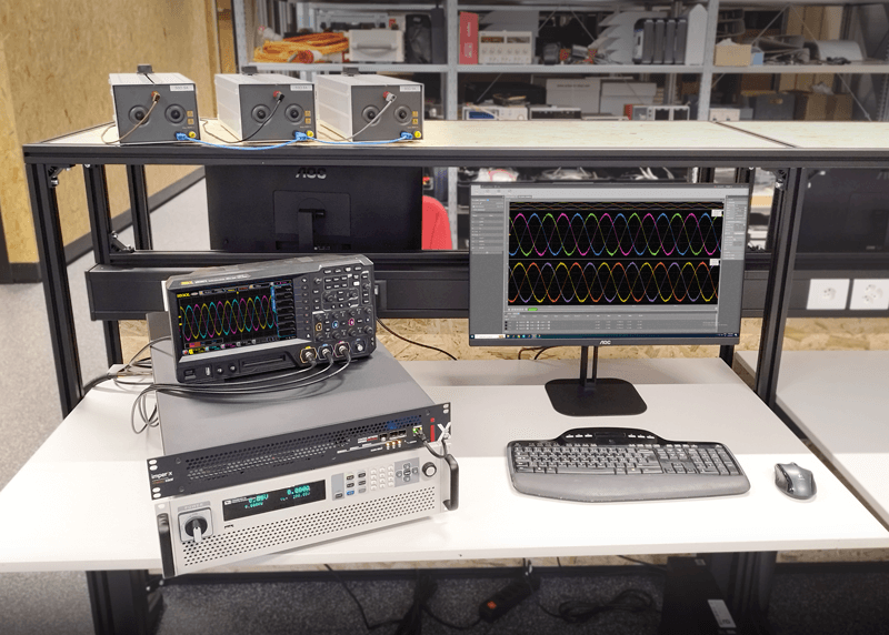
The TPI 8032 is an all-in-one product that integrates all the necessary components for running a two-level three-phase inverter, covering from the digital controller to the power stage. Its typical applications include grid-tied inverters and back-to-back converters. Multiple TPIs can work together or alongside other imperix controllers in various setups, covering a broad range of power ratings and supporting a wide range of microgrid applications.
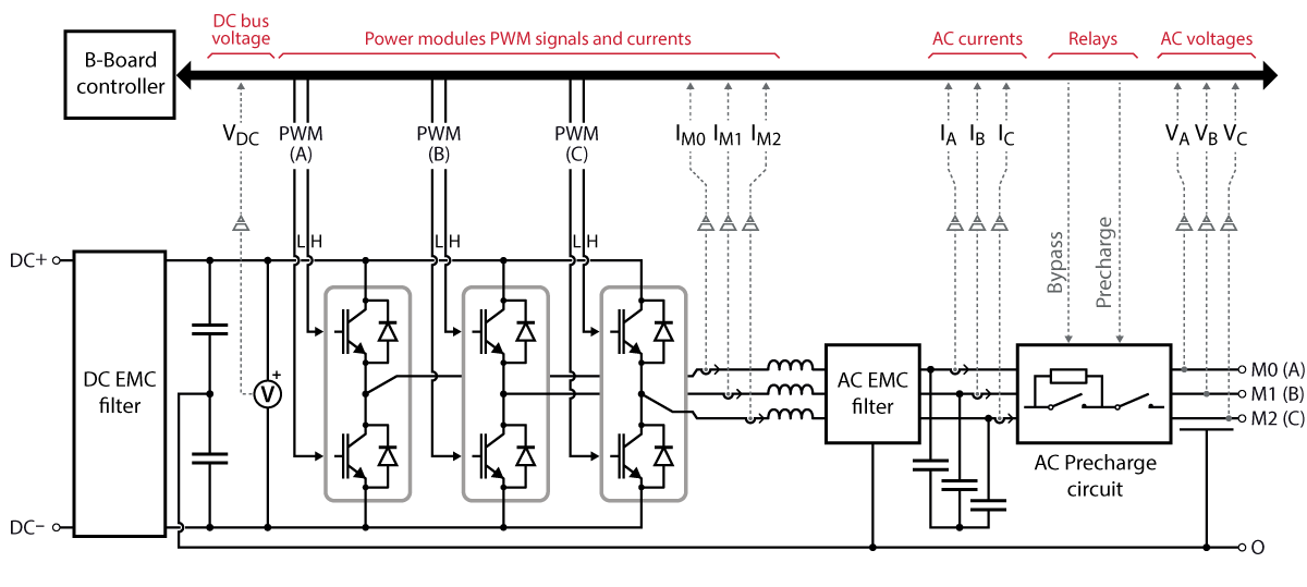
The power stage of the TPI 8032 is a three-phase inverter made of three half-bridge power modules based on Silicon Carbide (SiC) MOSFETs similar to the PEB8038 modules. An inductor of 0.95 mH is present at each module’s output (AC side). EMC filters are also present on both sides of the inverter to reduce electromagnetic interference (EMI) generated by the switching devices (more information is available in the datasheet). Finally, an integrated AC precharge circuit enables automated, safe precharging of the DC bus from the grid.
The control stage of the TPI 8032 is built around a B-Board PRO supported by a carrier board that connects to multiple sensors and redirects PWM signals to the power modules.
As shown in the figure above, the TPI 8032 has numerous embedded sensors. The currents flowing through the power modules \(I_{m,0,1,2}\) and the DC bus voltage \(V_{dc}\) are measured by the modules themselves, additionally offering over-current and over-voltage protection. Besides, three-phase current and voltage sensors are also present on the AC side for \(I_{a,b,c}\) and voltage \(V_{a,b,c}\).
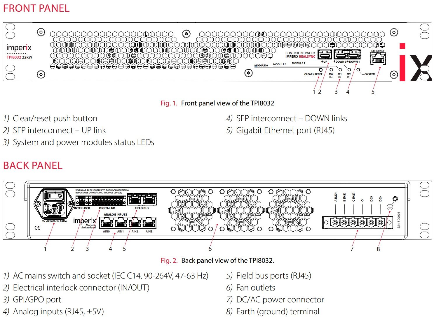
In addition to its internal sensors, the TPI 8032 also features 4 analog inputs for external sensors accessible via RJ45 connectors on the back panel. These inputs are similar to those present on B-Box controllers. They are compatible with all imperix sensors and can also be used with third-party products.
As for communication, the TPI has three SFP+ interconnect ports that enable ultra-fast communication between imperix controllers with RealSync. On the back panel, widely used communication protocols, such as CAN and UART, are available via the two field-bus connectors. Please refer to the datasheet for detailed information on all the port functions and parameters.
How to program the TPI 8032?
The TPI 8032 can be programmed either in C++ or with Automated Code Generation (ACG) tools from Simulink and PLECS. The programming procedure is identical to that for other imperix controllers, described in PN138. The latest version of ACG SDK can be downloaded at imperix.com/downloads/.
Within the Simulink and PLECS blocksets, a specific sub-library implements preconfigured blocks for the TPI8032.
These blocks encapsulate regular blocks and facilitate their configuration by hiding irrelevant hardware-related details, such as I/O mapping and sensor sensitivities. More details can be found on the following pages:
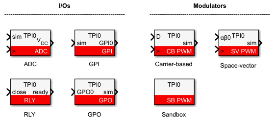
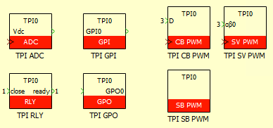
Using helper blocks is not required to program the TPI, as the hardware resources are still accessible with regular blocks, such as ADC and CB-PWM. However, it is recommended to use the helper blocks, as they are simpler to use and less prone to configuration errors. Besides, the TPI RLY block is necessary for the AC precharge circuit because there is no functionally equivalent block in the generic imperix blockset.
Once satisfactory simulations are obtained, the model must be compiled before it can be deployed to the controller. Cockpit then automatically launches and creates a new project with a pre-filled project name and executable file path. These steps are still identical to those for other imperix controllers, as presented in PN138.
The Ethernet connection to the host PC and IP address configuration can be done similarly to other imperix controllers using the default static IP address 192.168.222.22. When multiple devices are present on the same local network, the LED blinking feature in Cockpit may help identify the correct target. The detailed procedure is listed in accordions below.
- Make sure the TPI device to be programmed is powered ON.
- In Cockpit, open the Target explorer by clicking on the button next to Target IP.
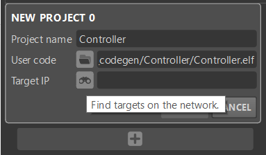
- The Target explorer window displays all the imperix controller devices in the local network. If the TPI device is not listed, click on the REFRESH button to search again.
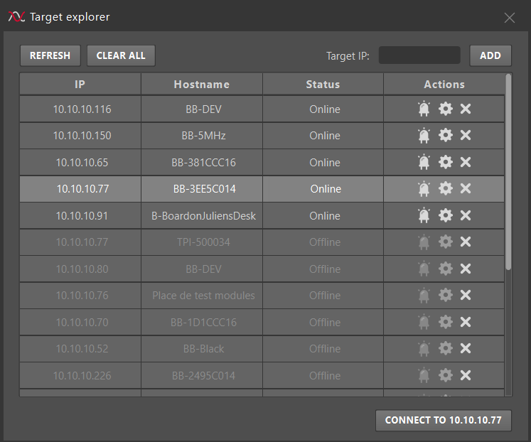
- To make sure the selected device is the correct target, click the LED button (the first button on the left in the Actions column) to blink the target’s LED. A window will pop up in Cockpit, and the SYSTEM LED on the front panel will blink green.
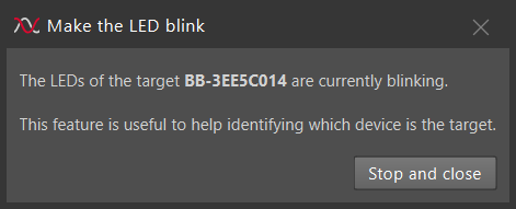
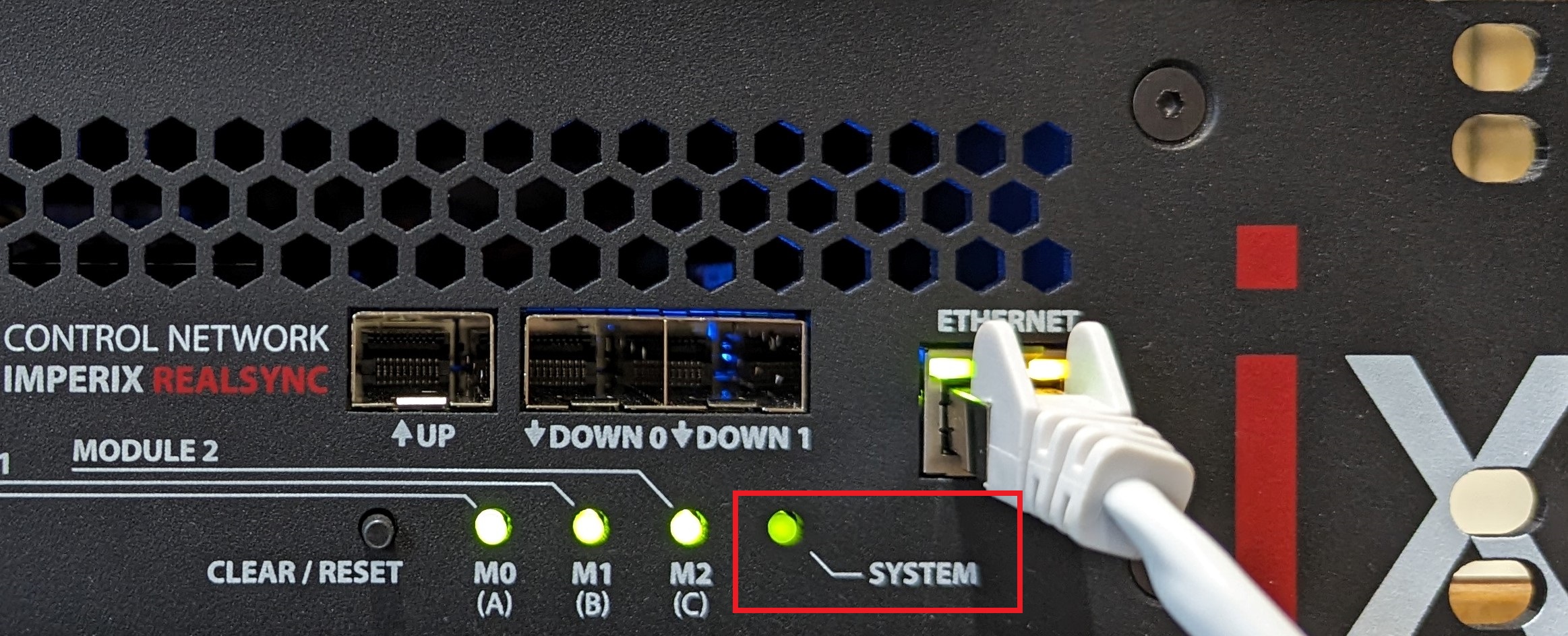
- Once the target is identified, click Stop and Close to stop the LED from blinking.
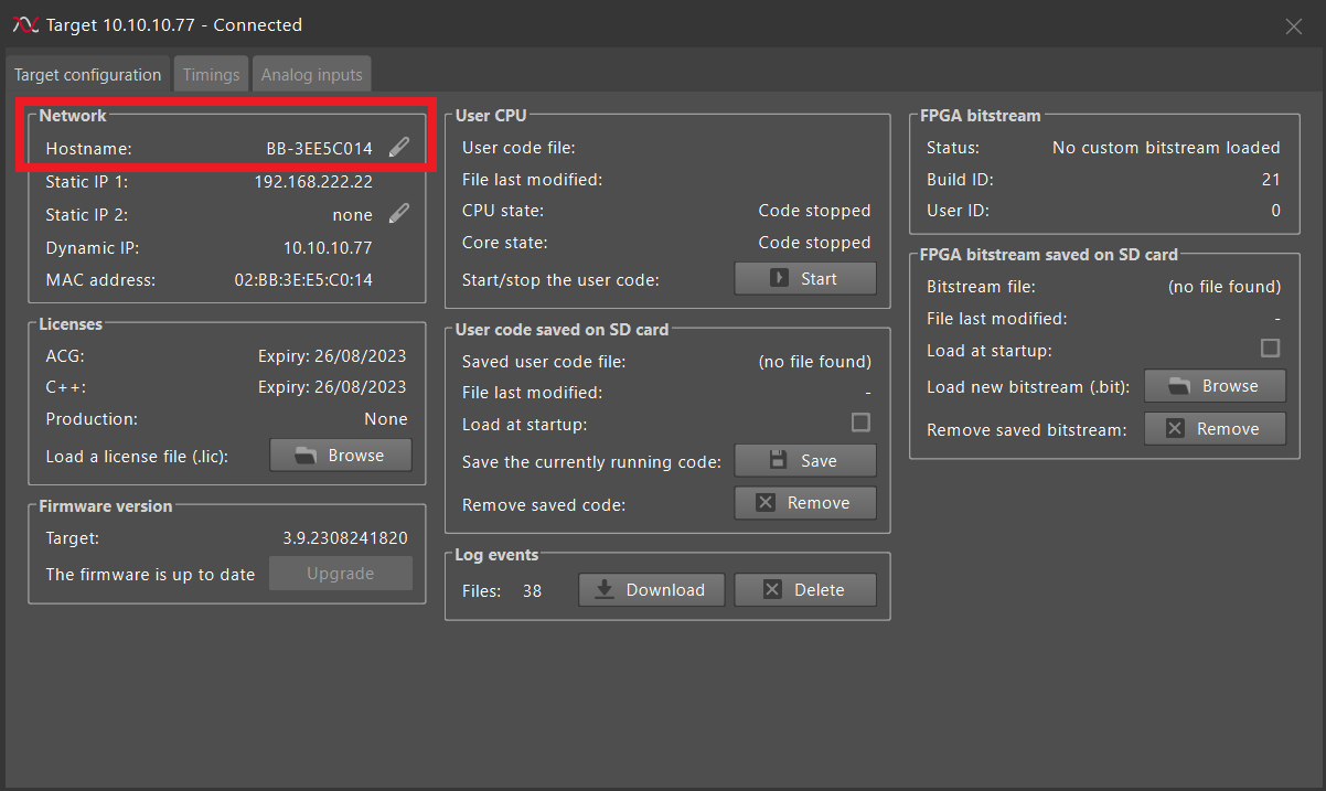
- For ease of future use, the TPI’s hostname can be renamed in the Target config window (by clicking the middle button in the Actions column). Note that the TPI has to be rebooted for the new hostname to take effect.
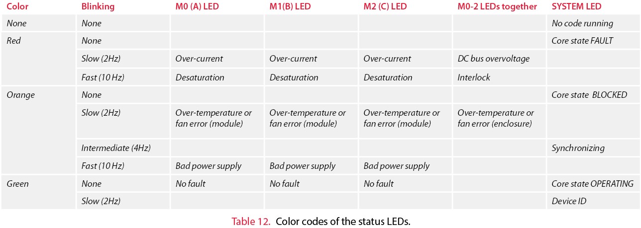
The front LEDs also indicate the TPI’s status while operating.
Instructions for safe use
Although TPI8032 has numerous built-in protections to ensure its safe operation in an experimental environment, following general safety guidelines, as summarized in TN181, is recommended. Additionally, the following accordions outline special precautions related to the TPI8032.
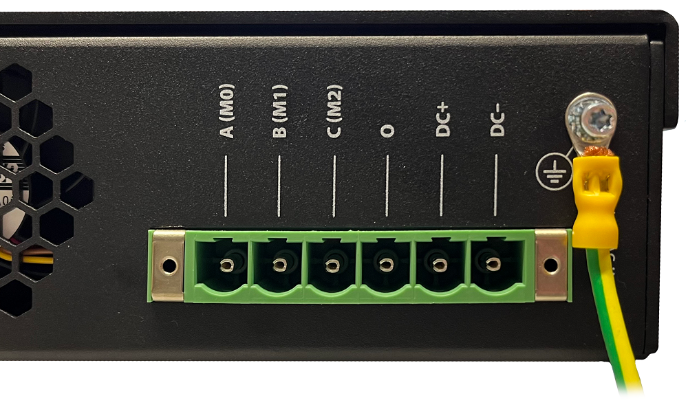
The PE terminal must be connected to the Protective Earth to ensure the system’s electrical safety and optimal EMC performance. Additionally, the earthing cable should be as short as possible and connected to the common ground with other devices in the setup (if any).
The TPI 8032 has built-in protections against overcurrent, overvoltage, and overtemperature on the power modules. The corresponding thresholds are dynamically configured based on the switching frequency and DC bus voltage, considering the derating of the converter and EMC filters. In general, two main factors cause the derating:
- As the switching frequency or the DC voltage increases, the average RMS current that the power modules can handle has to decrease.
- As the switching frequency drops below 50kHz, the maximum DC voltage must decrease to avoid saturating the common-mode inductors in the EMC filters.
The following figure shows the Safe Operating Area (SOA) of the TPI, considering the current derating of the power modules and the voltage derating of the EMC filters.
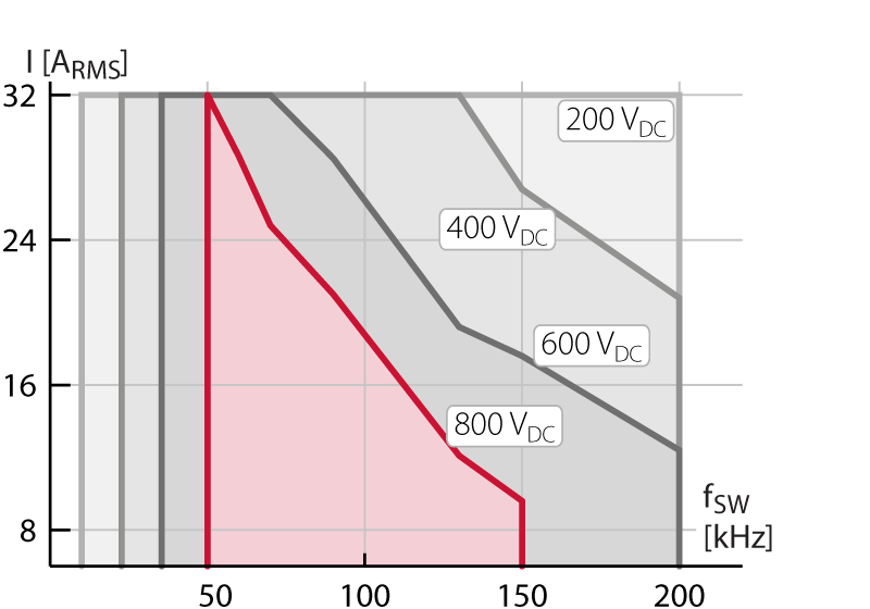
The B-Board controller enforces the SOA according to the converter’s switching frequency and the measured DC bus voltage. Once the SOA is exceeded, the TPI will enter the FAULT state and stop all the PWM outputs.
In addition, a common reason that may trigger the SOA frequency protection is a saturated PWM modulator, which can significantly increase the time between two PWM rising edges.
“Hello world” example with the TPI 8032
This page provides code examples and step-by-step instructions for use with the ACG SDK. Users unfamiliar with code generation from Simulink or PLECS should first refer to PN134 or PN135, respectively.
The required equipment for running the suggested first test is listed below:
- 1x TPI 8032 three-phase inverter
- Properly installed Simulink or PLECS environment with ACG SDK
- 1x DC power supply (50V to 800V)
- 3x power resistors (5Ω to 100Ω). The current rating depends on the DC voltage.
- All the necessary cables
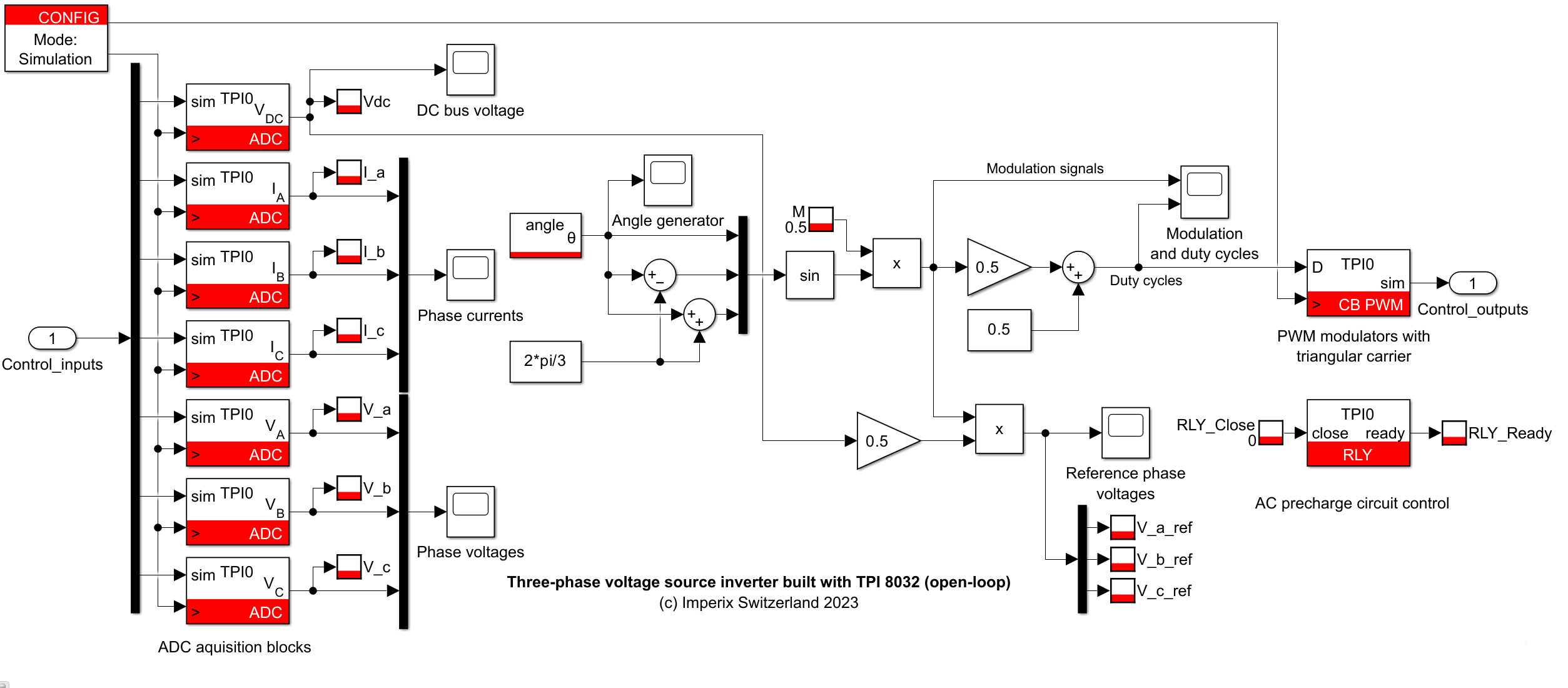
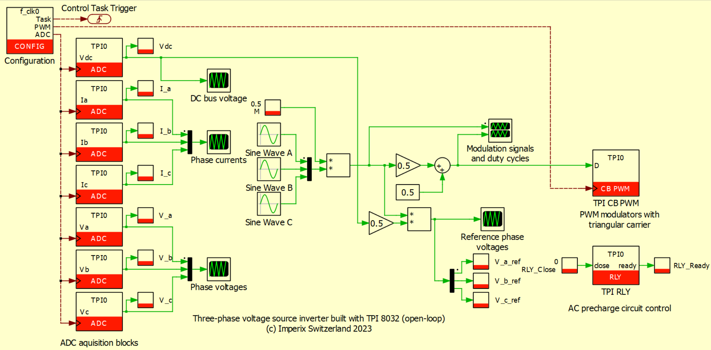
The Simulink and PLECS models provided below implement open-loop voltage generation for a three-phase VSI connected to a passive load.
Passive components sizing
Considering a DC bus voltage of 200 V, 50 Hz operation, and inductors of 0.95mH, a resistive load of 3x 8.5Ω guarantees a maximum output current of 8.3 A for a modulation index of 1:
\(I_{RMS}(M = 1) = \frac{\sqrt{2}}{4} \frac{V_{dc}}{\sqrt{R^2 + (2\pi fL)^2}} = 8.3\,\text{A}\)
| Chosen values | Suggested values | |
| DC Bus | 200V | 50-800V |
| Inductors | 0.95mH | Fixed value |
| Resistors | 8.5Ω | 5-100 Ω |
To ensure safe operation during this demo test, we suggest selecting \(V_{dc}\) and \(R\) such that \(I_{RMS}\) is always smaller than the current ratings of the TPI and the resistors even with modulation index \(M=1\).
Wiring the TPI 8032
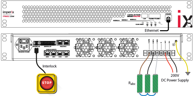
Starting from the front panel, connect the Ethernet port to the local network or directly to the PC. Then, on the back panel:
- Connect the Protective Earth (PE) terminal to the ground.
- Connect the DC- and DC+ terminals to the DC power supply. Double-check that the DC polarity is correct.
- Connect each AC terminal A, B, and C to one of the resistors, and then connect three resistors in a star configuration.
The figure below shows the complete wiring of the TPI 8032.
Building the model with ACG tools
… in Simulink
- Open the Simulink model. Open the Controller subsystem and set the mode to Automated Code Generation in the CONFIG block.
- Build the model (Ctrl + B). Upon success, Cockpit automatically launches.
… in PLECS
- Open the PLECS model. Check that the CLOCK_0 frequency is set to f_clk0 in the CONFIG block. The definition of the variable f_clk0 can be found in Simulation -> Simulation parameters (Ctrl + E) -> Initialization.
- Open the Coder Options menu by selecting Coder -> Coder options… (Ctrl + Alt + B). In the General tab, set the Discretization step size to 1/f_clk0. This ensures that the main interrupt rate is set to 1/f_clk0.
- Click on the Build button to build the model. It will automatically launch Cockpit.
Setting up the workspace in Cockpit
- Set the Target IP in Cockpit and click on Create to generate a new project. Use the LED blinking function to identify the target device if needed.
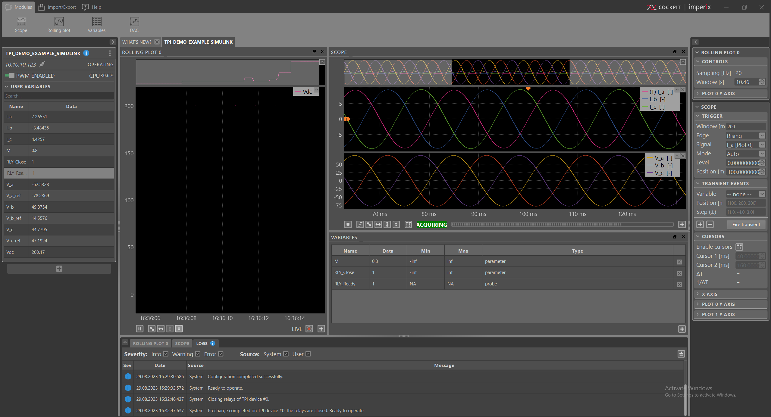
- Add a new rolling plot module, then drag-&-drop the Vdc variable to monitor the DC bus voltage. The rolling plot allows for monitoring the DC bus voltage over a long period.
- Add a new scope module and drag-&-drop the I_a, I_b, and I_c variables. The scope can display every sample made available to the control.
- Add a new subplot to the scope module by clicking the ‘+‘ at the bottom right and drag-&-drop the V_a, V_b, and V_c variables.
- Add a new variables module and drag-&-drop the RLY_Close, RLY_Ready, M variables. This way, the main parameters are easy to find.
Step-by-step test procedure
- Ensure the relays are open by checking that the RLY_Close variable is set to ‘0’.
- Turn on the laboratory DC source and gradually increase the DC bus voltage from 0 to 200V. Check with Cockpit that Vdc matches the source voltage.
- Close the relays by setting the RLY_Close variable to ‘1’. Check that RLY_Close goes to ‘1’, which indicates the relays are triggered and ready to operate.
- Check that M = 0.5. Enable the PWM outputs from Cockpit and check the peak value of V_a, V_b, V_c by \(V_{a,b,c,peak}=\frac{M}{2}V_{dc}\). Check the peak value of I_a, I_b, I_c by \(I_{a,b,c,peak}=\frac{V_{a,b,c,peak}}{R}\).
- Set M to 0.8 and check that V_a, V_b, V_c, and I_a, I_b, I_c follow the new reference.
- At the end of the experiment, disable the PWM outputs first, and then open the relays by setting the RLY_Close variable to ‘0’.
- Reduce the output of the DC source to 0 V. Double-check in Cockpit that the DC bus is fully discharged.
The screenshot below shows how the workspace could look at the end of the procedure.
To go further…
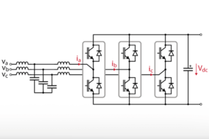
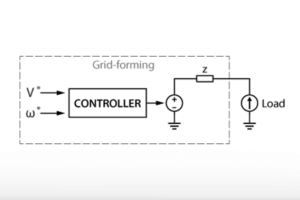
The TPI 8032 is particularly suited for AC microgrid applications. Notably, the article on the Active Front End covers the fundamentals of grid-connected operation and the necessary precautions related to the precharge circuit. It is recommended to read this page first before running the TPI with the grid.
With respect to microgrid applications, the following articles are also interesting starting points:
 By Shu Wang • January 24, 2024 • TN166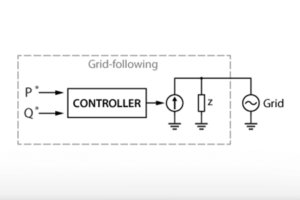
 By Daniel Blardone • January 30, 2024 • TN168